Sunday, 23 May 2021

I love cheap thrills: WiFi OTA for Microchip PICs


Cheap Thrills - Sia


"Come on, come on, turn the radio on
It's Friday night, and it won't be long
Gotta do my hair, put my make-up on
It's Friday night, and it won't be long
'Til I hit the dance floor, hit the dance floor
I got all I need
No, I ain't got cash, I ain't got cash
But I got you, baby
Baby, I don't need dollar bills to have fun tonight
(I love cheap thrills)" - 
Sia, Cheap Thrills

Firmware Over The Air programming (OTA) is all the rage with Internet of Things (IoT) devices. Ongoing privacy and security issues make it almost mandatory that they be upgradeable after installation. That usually means OTA upgrades using a smartphone App or a desktop browser.

For a hobbyist, or just plain fast and cheap development, few systems beat the ESP8266-based IoT OTA, ArduinoOTA. The ESP8266 has a few flaws. It is difficult to operate on small batteries: sleep mode still requires milliamps and while using WiFi it can surge to 100mA. Also, executing the WiFi stack takes priority and this sometimes causes interrupt service routines to have unpredictable delays. Most applications are OK with this, unless your code is time-critical like trying to a dimmer triac while connected to WiFi.

Microchip CPUs in particular shine at low-cost, low-power performance and raw horsepower. But their WiFi OTA solutions tend towards the later, more expensive models. Wouldn't it be great if we can have OTA for the Microchip CPU, say a PIC16F84 or even a PIC16F1705 if you want to roll C code? In particular the latter has a mouth-watering dedicated zero-crossing detect (ZCD) interrupt which would be very handy for a flicker-free dimmer or a heavy-duty switching of inductive loads.

It turns out this can be done. We build an ESP8266 into a Microchip PIC system and use the former's WiFi capability to program the PIC. WithArduinoOTA, both the ESP8266 and PIC have OTA. Microchip's recommendation is to use a bootloader, ie reserve dedicated program space in the PIC for  bootloader so that it can be programmed via its serial port. This possible for the PIC161705 but would would be a very tight squeeze for the PIC16F84 - the low-end PICs are usually short on memory. In addition the bootloader would be unable to change certain startup configuration bits.

PICkit 2 programmer (left) connected to a target system via its JTAG port


There is another way to do serial programming for a Microchip PIC: most of them support In-Circuit Serial Programming or ICSP. This is the same method a Microchip Programmer like the PICkit 2 uses. An ESP8266 program speaking ICSP to the PIC will be able to program it without resorting to a bootloader. It turns out this has already been done: mengstr's esppic hackaday project. His source code is in github.

This post really has little to add to mengstr's work, except maybe a little documentation on how to get it up and running, and with luck add some support for the PIC16F84 or even the venerable PIC16F57.

Schematic for target CPU board

The ESP-12E to JTAG programming connector pinout is:

               Pickit2                                 ESP-12E

            Pin 1     MCLR/Vpp               D0/GPIO16

            Pin 2     Vdd                           3V3

            Pin 3     Gnd                           Gnd

            Pin 4     Dat                            D1/GPIO5

            Pin 5     Clk                            D2/GPIO4

            Pin 6     N/C

This way the PIC16F1705 development board can be programmed from both the PICkit 2 and the ESP-12E. The JTAG port also lets you run the target system directly from the PICkit 2. Not having to unplug the target system and hooking it up to another power source greatly speeds up the development cycle.

PICkit 2 might need an updated PK2DeviceFile.dat file for the PIC16F1705. In my case I use pk2cmd with Linux. pk2cmd needs to be updated to work with Gerhard Bertelsmann's version of pk2cmd.  It is tucked away in a gigantic 300MB misc repository, so I copied it here for your convenience. To compile, simply:

$make linux

To test, plug the target CPU board into the PICkit 2 JTAG port.
$./pk2cmd -PPIC16F1705 -GC
Read successfully.

Configuration Memory

3EFF  3F87

Operation Succeeded

To program,

$./pk2cmd -PPIC16F1705 -Fblink_led.hex -M
PICkit 2 Program Report
18-5-2021, 9:38:13
Device Type: PIC16F1705

Program Succeeded.

Operation Succeeded

To run,

$./pk2cmd -PPIC16F1705 -GC -T -R

To stop running (in order to unplug)

$./pk2cmd -PPIC16F1705 -GC

To compile my program I used sdcc sample code from Diego Herranz. For Debian sdcc installation is simply:
#apt-get update
#apt-get sdcc

For Slackware it is a little bit more involved. We need the pic14-port ad pic16-port so first get the gputils source code.
$./configure
$make clean
$make
$su -c "make install"

Next get the sdcc source code from sourceforge

Next, untar it:
$tar -xvjf sdcc-src-3.9.0.tar.bz2

Then build it:
$./configure
$make -j 10
$su -c "make install"

Here is Diego Herranz's pic14/1.blink_led/blink_led.c modified slightly for the PIC16F1705:

// Copyright (C) 2014 Diego Herranz

#define NO_BIT_DEFINES
#include <pic14regs.h>
#include <stdint.h> 

// Oscillator Selection bits (INTOSCIO oscillator: I/O function on RA6/OSC2/CLKOUT pin, I/O function on RA7/OSC1/CLKIN),
// disable watchdog,
// and disable low voltage programming.
// The rest of fuses are left as default.
//__code uint16_t __at (_CONFIG1) __configword = _INTRC_OSC_NOCLKOUT & _WDTE_OFF & _LVP_OFF;
__code uint16_t __at (_CONFIG1) __configword = _FOSC_INTOSC & _WDTE_OFF & _LVP_OFF;

#define LED_PORT PORTCbits.RC0
#define LED_TRIS TRISCbits.TRISC0

// Uncalibrated delay, just waits a number of for-loop iterations
void delay(uint16_t iterations)
{
        uint16_t i;
        for (i = 0; i < iterations; i++) {
                // Prevent this loop from being optimized away.
                __asm nop __endasm;
        }
}

void main(void)
{
        LED_TRIS = 0; // Pin as output
        LED_PORT = 0; // LED off

        while (1) {
                LED_PORT = 1; // LED On
                //delay(30000); // ~500ms @ 4MHz
                delay(5000); // ~500ms @ 4MHz
                LED_PORT = 0; // LED Off
                //delay(30000); // ~500ms @ 4MHz
                delay(5000); // ~500ms @ 4MHz
        }
}

To compile it:
$sdcc -mpic14 -p16f1705 --use-non-free blink_led.c

If you do not want the hassle of compiling it, here is the hex file:

:020000040000FA
:10000000000080310328DE30FB008030FC008030AF
:100010008031832080312C00A1007C08A000E030DA
:10002000A2008030A3002C002008A4002108A50015
:10003000FF30A007031CA10324082504031980280E
:1000400004302207A400A501A50D2308A507240854
:10005000FB002508FC0080308031832080312C009B
:10006000A7007C08A6002208FB002308FC008030C3
:100070008031832080312C00A900A5007C08A800D5
:10008000A40002302207A400A501A50D2308A5079E
:100090002408FB002508FC0080308031832080315B
:1000A0002C00A500AB007C08A400AA002C002608A8
:1000B000AA002708AB00FF30A607031CA7032A08E5
:1000C0002B0403197A282808FB002908FC0080303B
:1000D0008031A02080312C00AA002408840025084B
:1000E00085002A088000A80A0319A90AA40A03198E
:1000F000A50A562806302C00A2070318A30A1328C5
:100100008031B2280800003A03198B28803A03197D
:100110009328FC0100347B0884007C0885001200D1
:10012000FC00000808008031AD20FA00FB0FFC0342
:10013000FC0A8031AD20F9007A08FC00790808003B
:10014000003A0319A728803A0319AD2800347B0828
:1001500084007C088500000808007C088A007B0871
:100160008200080021000E1020000E1020000E1446
:100170008830FC0013308031C820803120000E1000
:100180008830FC0013308031C8208031B628080048
:100190002C00AD007C08AC00AE01AF012C002D0896
:1001A0002F02031D02322C082E020318DD28000046
:1001B0002C00AE0A0319AF0ACE280800013400341F
:0E01C000E634003430340634013400340034A8
:020000040001F9
:02000E00E41FED
:00000001FF

Next we move on to the Arduino IDE to compile mengstr's esppic code over at his github repository. The ESP8266 code is in https://github.com/mengstr/esppic/tree/master/esppic, and you need to set the compile settings for NodeMCU ESP-12E, CPU speed 80MHz. 

You will also probably need to pull in a library from Websockets library from here. In addition you will need to put in the same local Arduino code directory, a sub-directory named data and fill it with the files from mengstr's https://github.com/mengstr/esppic/tree/master/assets. They are necessary for the webserver code for the ESP8266. 

In the Arduino IDE, go to Tools->ESP8266 Data Upload and program the SPIFFS data/ files. Next, program the ESP8266 NodeMCU via the USB port. It comes up as a WiFi Access Point, so connect to it, maybe with your smartphone or laptop. With a browser, connect to http://192.168.4.1 and type in your WiFi SSID and password.

NodeMCU ESP-12E wired to JTAG port of PIC16F1705 target CPU board


Now power off and connect it to the JTAG port of the PIC16F1705 target board. Make sure in Arduino IDE you have the Debug Monitor active at the USB serial port, as it will come up with the IP address as it starts up. Say it is 12.34.56.78. With a browser, connect to http://12.34.56.78.

You should see something like this in the Debug Monitor :

Connecting to wifi using default info
..
Successfully connected. IP=12.34.56.78
handleFileRead(/)
/index.html (0 bytes) Open:53 Stream:1 Close:0
handleFileRead(/)

Screenshot of programming webpage


You should first try reading the CONFIG1 and CONFIG2 registers. In my case I had trouble getting a  brand-new blank PIC16F1705 to work; I had to first program it with the PICkit 2. If it works, the browser should show:

MEMORY DUMP
DEV ID : 3055
DEV REV: 2003
CONFIG1: 1fe4 (0001 1111 1110 0100)
CONFIG2: 3fff (0011 1111 1111 1111)
USER ID: 3fff 3fff 3fff 3fff

Followed by a memory dump, something like:

0000: 0000 3180 2803 30DE 00FB 3080 00FC 3080 3180 2083 3180 002C 00A1 087C 00A0 30E0
0010: 00A2 3080 00A3 002C 0820 00A4 0821 00A5 30FF 07A0 1C03 03A1 0824 0425 1903 2880
0020: 3004 0722 00A4 01A5 0DA5 0823 07A5 0824 00FB 0825 00FC 3080 3180 2083 3180 002C
...

To program use a browser, or navigator or Konqueror to drag the hex file over to the programming icon. I could not get mine to work with Google Chrome, but Konqueror or Firefox works for me.

Sometimes esppic locks up during a memory dump or programming; I find it best to simply power-cycle it and start afresh. For some reason I could not get it to recover from an error condition. Notice the PIC16F1705's programming datasheet recommends using 5V while programming and we are using 3.3V so maybe this caused the flakiness. You can at a pinch wire it to the ESP-12E's 5V, but I would not recommend long-term usage like that as the ESP8266 datasheet says it is a 3.3V device and mught get over-stressed. It would be instructive to try the PIC16LF1705, which is an explicitly low-voltage version.

There you have it, WiFi OTA for the Microchip PIC16F1705. I don't need dollar bills to have fun tonight. I love cheap thrills. 

Happy Trails.

Wednesday, 12 May 2021

Development System for the ancient Microchip PIC16F57 CPU


Microchip PICkit 2 Programmer with target system

The Microchip PIC16F57 is an ancient CPU, long superceded and only grudgingly sold by Microchip Inc. Indeed there is currently a 2-month wait for them. It has a tiny 2K word program memory and a microscopic 72 bytes RAM. Too small to use with C, To program it, you would need assembly language. Why would I want to waste time on something like that? 

I have a remote gate opener ('autogate') which I tinker with unmercifully. It is also underneath an powerhead mains power pole which seems to get struck by lightning a few times a year, so over the years I accumulated a stack of dead S-1 controller boards which I usually repair and reuse. Except for those few which had dead CPUs.

S-1 Autogate Controller Board

Now they are cheap enough: RM100 (USD25) will buy you one online. But repairing these last boards meant replacing the CPU, which meant writing the program for it. After some effort, I noticed that the CPU footprint is an exact match for the Microchip PIC16F57, and I even have one in my CPU tray.

Writing the program also means I can upgrade the CPU to a newer one, and maybe add WiFi connectivity as well. And since the Chinese can sell me the board cheaper than I can make it, it does not make sense to make my own PCB. To upgrade it I would first have to replicate its functions, and that means writing the program from scratch.

But before I can even do that I have to find an Assembler, device programmer and build a little target system (PIC16F57 CPU board) just to make sure the toolchain works.

Microchip's MPLAB Version 8.33 (an equally ancient version running on Microsoft Windows XP) works for me. It comes with the MPASM assembler which happened to support the PIC16F57. You can try your luck with the latest and greatest MPLAB, but if it does not work out, you can get Version 8.33 from the Microchip MPLAB archive. I run a Windows XP image from a Qemu-KVM virtual machine and use pk2cmd with my PICkit 2 programmer, but you will probably be quicker off the mark with a Windows XP laptop.

The next thing you need is a little PIC16F57 (ie target) board just to accept the PICkit 2 connector and also run a small test program.  

PIC16F57 target system


Then you need the test program which you feed into your MPLAB assembler and produce the hex file the PICkit 2 needs to program the CPU. Usually you can find such sample programs in the great wide Internet but for some reason, not for the PIC16F57. You can find the schematics, hex file and source code here in my github repository.

To program the PIC16F57 I use:

$./pk2cmd -PPIC16F57 -Fledblink.hex -M

To run it I use:

$./pk2cmd -PPIC16F57 -GC -T -R

Some notes of caution: my experience is a Microchip CPU in a new target system can be hard to start. The combination of your choice of oscillator affects the Power-on Reset Timer delay. The MCLR reset circuit also changes things. You also need to sort out you Reset and Watchdog Timer vectors without which you program will not start. Once you get past that it is usually plain sailing. Using a Microchip Development Kit makes real sense here, but they have long since abandoned the PIC16F57. Also having a known good toy program helps when you are trying to start the CPU.

Despite having only 2K the PIC16F57's memory is also segmented. The simplest way is to ensure the program sits within page zero 000-1FF. This is because subroutines calls only work within page 0. You can next just 2 levels of subroutines.

Lastly the digital output pins are set and cleared (ie BSF and BCF) using a Read-Modify-Write mechanism. This means the CPU does not keep a record (ie a register) of your IO bits. It also accesses IO 8 bits at a time and if it executes a write, it will first read the whole byte from the external circuits, modify the read data and writes back the 8 bits. This can have unexpected effects if you are not running within the electrical operating limits (ie driving too much current into an LED). Also a CPU IO write followed immediately by a read may execute too fast for the external circuit.

The RC system clock circuit is a little hard to time accurately because of its inherent inaccuracy and component tolerances. If your LED does not blink, you might need to adjust the delay intervals. If that fails, seek to dim the LED rather than blink it.

This is a hard-core RISC instruction set, running in a Harvard Architecture (ie program and data busses are separate). There is usually no substitute to reading every single word in the datasheet.

If this is your first time with assembly language, congratulations. You have talked to a CPU in its own language, mano a silicona, and it understood you. 

Good Luck, and Happy Trails.   

Wednesday, 5 May 2021

SMD Hot-Air Rework Station Repair


Ya Xun Hot-Air Rework Station cost just RM209 (less than USD50) 

Last year I bought a cheap hot air rework station. It was probably not a good idea - I have never used one before, and this being pandemic season, I would be on my own. My eyesight is not getting any sharper but the electronic components are definitely getting smaller. On the other hand, all the fun stuff nowadays, like ESP8266, Aduino and Raspberry Pi all seem to use Surface Mount Devices. And most compellingly, SMD parts are much cheaper than their through-hole equivalents. 

Some SMD components are just about manageable using old-school soldering irons


I found myself buying soldering irons with smaller and smaller tips, right down to 0.5mm. With discrete SMD I simply used two irons (I would have used more but I ran out of hands): you can often heat up the entire thing and lift it clean off with two irons. To solder a new SMD part in I used the 0.5mm iron. SMD ICs were a problem: sometimes you just could not heat up all the leads with two irons. But if I had new ICs on hand I would simply cut the IC off the printed circuit board. You then removed each soldered lead one by one. 

You need a small and really sharp pair of micro-cutters. Anything less and the leads tend to get ripped off along with the tiny PCB pads. That cutter you never lend out or use for anything else. You guarded it jealously and threatened anyone with immediate bodily harm if he tried to take it.

Duratool's micro cutter: don't leave home without it. 


But QFN and BGA SMD packages were quite another thing. The contacts and PCB pads are underneath the body, and only a hot air gun will get them off without damaging the PCB. Well, I could sneak the PCB into the wife's oven in the kitchen, but this tends to remove all the parts. To inspect the soldering, one would need nothing less than an X-ray machine. 


QFN (Quad Flat No-lead) IC

BGA (Ball Grid Array) IC

Even when there are no BGA or QFN parts, sometimes there is simply not enough room to place the irons, and neighboring parts may get moved, burnt or worse. But then came a China siren to lead me into temptation: at only RM209 (less than USD50) the Ya Xun 850A+ cost about as much as a Raspberry Pi 4. The clunky box may even be an advantage - it is less likely to use SMD parts, which makes it repairable with soldering irons.

China temptress

In about a year it failed completely: it blew its fuse. After replacement, its temperature LED no longer lit up and the hot air flow is no longer adjustable. I whipped off the cover and got the PCB out. Usually I could figure put most PCBs but looking at the parts mounted. But only if I am already familiar with them. There is just one problem: I had never worked with triacs before and this board had two, in essentially AC power "dimmer" type circuits. This means to make any sense of it I would need to first trace out the schematic. Oops.

YX850A+ Controller PCB: old-school single-sided PCB with through-hole parts

Warning: this repair deals with lethal voltages. Do not attempt unless you have been properly trained!

The PCB used old-fashioned through-hole components as expected. Even better,  the PCB is single-sided: it only has traces on the bottom (ie solder) side. This makes it easy to trace the leads; PCB traces o the component (ie top) side will run under the parts and be obscured. Single-sided PCBs are also easy to desolder. 

Tracing the PCB was not so bad, but having worked with a human PCB designer for over 10 years, hand-drawing schematics felt lame so it seemed like a good idea to install geda again. Two weeks later, armed with the schematics and a wobbly knowledge of triacs and diacs, the repair work began.

The first problem was the internal wiring was badly crimped; the wires were the wrong sizes and the resulting crimped joints were loose, in particular those at the front panel switch.

Loose crimp connectors at the panel switch (top) and temperature sensor wiring (bottom)

The front panel main switch switches in both mains AC and 12V DC to the PCB and loose joints here cannot be healthy for the triacs. And sure enough the triac Q2 BT136-600 is shorted Gate to T2. The LED D1 which indicates airflow was also shorted, together with its series rectifier D2 (1N4007). Unusually, the LED appeared to be driven directly by the triac output AC and is probably more sensitive to line surges. The PCB trace from D2 to Neutral was melted a good 4mm. 

BT136 triac and associated components

The gate drive diac, D4 (DB3) and its series capacitor C5 (120nF polyfilm) were also shorted. Now triacs are turned on using the gate, but can only be turned off by letting its load current drop to zero, which means interrupting its input mains. This is done using a relay K1 (HK4100F-DC12V-SHG an Omron G5V-1 equivalent). The relay is powered from 12V output from U3, an LM7812 linear regulator which was also shorted input to output.

The other triac, a BTA12-600 supplying the heater seems to be fine. The heater LED failure was due to a loose temperature sensor wire. The heater is probably a lot less inductive than the air pump motor. It also helps it is triggered from another optically-isolated triac U2, an MOC3023. Interestingly the MOC3023 drives the main triac's gate using a series rectifier D4 (1N4007) which means it only puts out half the AC waveform and pretty much guarantees the BTA12 turns off during the other half cycle. The MOC3023 is in turn driven by the temperature sensor via U1, an HA17358 (probably an LM338 workalike) which seems none the worse for wear despite being exposed to unregulated 25Vdc from the shorting LM7812. The 40V maximum of the LM338 probably helps.

Repair was easy. The parts easily dismounted and replaced. The dodgy crimp connectors were soldered to their wires. Replacement parts were cheap and arrived quickly despite the pandemic-induced parts shortage. The Malaysian branch of Element14 in particular offered free delivery, in contrast Digikey wanted USD89 to deliver a USD2 part.

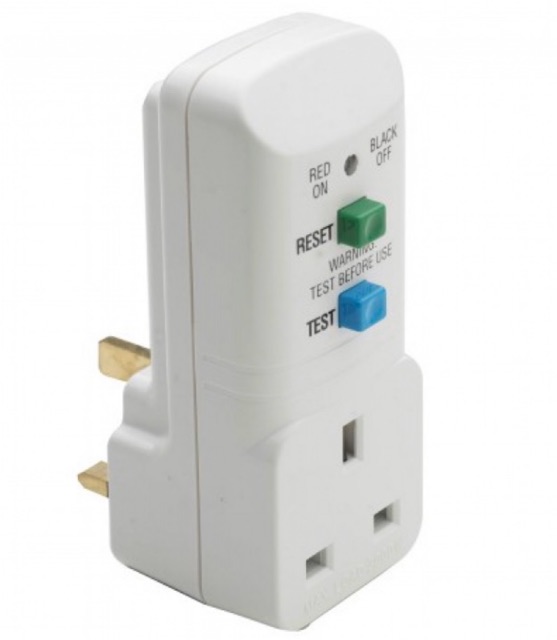
To test, I used a 300VA isolation transformer dialed down to 220Vac (China boards are rated for 220V; Malaysian grid is 230V but I am at the very end of the mains power line at a feisty 240V). For additional safety I also used a portable ELCB (RCD to Americans). Since some semiconductors (usually mains bridge rectifiers) are connected directly to mains AC sometimes there is a short from  Live to DC ground, and an ELCB will pick this up.

Portable ELCB

An isolation transformer is a two-coil transformer (ie not an autotransformer) putting out the same voltage level as its input. If the output is shorted, the current is limited by the magnetic flux saturating in its core, limiting power delivered to its VA rating. 

110Vac Isolation Transformer. Note the Earth line passes through but Live and Neutral are isolated. 


It often lets you diagnose faulty boards before it completely burns out. 60VA, or even 30VA are very handy ratings, and the idea is to progressively work up to the full device rating. I always make my own; a handy way is to use two regular (ie step-down) transformers connected back to back. To dial down the output voltage you will need to use a variable transformer to drive the isolation transformer.

2000VA Isolation transformer from Carroll & Meynell


Testing was straightforward except for one thing: the air pump continued to run despite the panel power switch being turned off. Despite having used it for a whole year, I did not really notice if it did that before. My excuse was I was struggling with tiny SMD parts. Having the air pump run meant the BT136 is on. Was the relay turning off?

Air pump relay circuit

I needed to make some live measurements. This is never a good idea when dealing with stuff connected to mains AC. The isolation transformer protects the repair item but will easily deliver a fatal shock to a human (50mA or 15VA will ruin your day, probably your life) . The mounting wires are short and the board has to be mounted vertically which means reaching past exposed live bits to probe.  

Thus far I had looked for defective parts the safe and preferred way: offline, unpowered and using a digital multimeter. If you suspected something you took it out and make some more measurements. When testing I powered up at low VA, operated the panel knobs and switches and avoided touching exposed parts. 

NPN transistor Q6 (SS8050) was an immediate suspect - with the panel switch off, its collector was 6V, way lower than the 12V if it were off. Maybe it was leaking? It tested OK dismounted: both semiconductor diode junctions seemed OK, but maybe it was partially leaking? I replaced it with a generic 2N2222 (watch it: ON Semi produces a PN2222 with reversed leads unlike my KSP2222A), but there was no change; the air pump kept running even though the panel switch is off.

An examination of the circuit provided a clue. In addition to switching in mains voltage, it also switched on 12V to Q6 (and the opamp). The capacitor C6 is 220uF and will store a walloping charge and R19_2 measures about 100K in-situ but is probably higher (the color codes are faded with heat). When switched off, it will ensured it discharged slowly into the base of Q6. The time constant is in the order of 22 seconds. And always fearing a defect I had been quick to cut off power to  the isolation transformer while testing.

Using this formula, my Change is 95% (12V to 0.6V) at time constant 22 will result in a delay time of 64.8s. I assembled and tested it again; and sure enough after a long minute the air pump went off. But why would it want do that? It is somewhat misleading to have the power on even after the panel switch is off.  The manual for a similar system yielded this clue:


Ah, that was unexpected, but at least it was not broken. I would recommend you spend that minute, set the airflow to maximum and wait for the air pump to finish doing its thing, and then turn the YX850A+ off at the power socket, for the manual goes on to say:


An auto-disconnect would be nice, maybe a few seconds after the air pump turns off. So would a thermal cutoff switch. And the triac heatsinks looked puny with the cooling fins horizontal instead of vertically where they would do most good. But that is a project for another day. 

There you have it: Hot-Air SMD Rework Station Repair.

Happy Trails.


Friday, 16 April 2021

USB over IP: How to remote-access your USB devices over the network


First appearing in 2005 in Takahiro Hirofuchi's kickass paper, there are much better guides on USB/IP, like Linux Magazine's, Ridgerun's, etc. From 2009 USB/IP was accepted into mainline Linux kernel and up-to-date documentation on it tends to get lost in the Linux haystack. The wrinkle here is USB/IP running on Slackware 14.2-current as of July 2019. Unlike Debian/Ubuntu you cannot usually seamlessly install USB/IP (or most other things) on Slackware. A little DIY is in order.

I know that is cold comfort compared to Debian's 'apt install'. Indeed, Slackware too has its (a little rickety) SlackBuild scripts. But in USB/IP case there is no SlackBuild as it was already included in the kernel. Well, after a fashion.

But take heart: in 30 years of Slackware I seldom fail to install the things I want. This is a chance to poke a little into the innards of Linux. You have the source code in all its glory. And it is built beautifully - I say this as one who has seen Microsoft Windows NT source code [shudder]. 

And the experience will prove useful in the rare instances Debian's installs fail, like the time I installed the Java development kit and could no longer log into my desktop. This means when things fail the same methods work: paste the error into google and look for the patches and workarounds. But I digress; back to USB/IP.  

I should test my Acer aspireM3's USB webcam before the install breaks things:

# mplayer tv:// -tv driver=v4l2:width=640:height=480 -vo xv -tv device=/dev/video1

Let's verify that my Slackware kernel actuall has USB/IP:

root@aspireM3:~# ls -lR /usr/src/linux/ | grep -i usbip
-rw-r--r-- 1 root root  1172 Jan 26  2019 sysfs-platform-usbip-vudc
-rw-r--r-- 1 root root 23365 Jan 26  2019 usbip_protocol.txt
drwxr-xr-x 2 root root  4096 Jan 26  2019 usbip/
/usr/src/linux/drivers/usb/usbip:
-rw-r--r-- 1 root root 18694 Jan 26  2019 usbip_common.c
-rw-r--r-- 1 root root 10117 Jan 26  2019 usbip_common.h
-rw-r--r-- 1 root root  3969 Jan 26  2019 usbip_event.c
drwxr-xr-x  3 root root   4096 Jan 27  2019 usbip/

Looks good. A look at the kernel's config file shows that the binary has not been left out at compile time:

root@aspireM3:~# grep -i usbip /usr/src/linux/.config
CONFIG_USBIP_CORE=m
CONFIG_USBIP_VHCI_HCD=m
CONFIG_USBIP_VHCI_HC_PORTS=8
CONFIG_USBIP_VHCI_NR_HCS=1
CONFIG_USBIP_HOST=m
# CONFIG_USBIP_DEBUG is not set

And finally, locate the kernel modules (ie device drivers) themselves:
# ls -l /lib/modules/4.19.18/kernel/drivers/usb/usbip
total 128
-rw-r--r-- 1 root root 22576 Jan 27  2019 usbip-core.ko
-rw-r--r-- 1 root root 42480 Jan 27  2019 usbip-host.ko
-rw-r--r-- 1 root root 58016 Jan 27  2019 vhci-hcd.ko

And it runs OK:
# modprobe -v usbip-core
insmod /lib/modules/4.19.18/kernel/drivers/usb/usbip/usbip-core.ko

Let's launch the USB/IP server daemon:
# usbipd -D
-su: usbipd: command not found

Oops. The userspace binaries are not installed. Let's see if my Slackware installation has the userspace source code:
# ls -l /usr/src/linux/tools/usb/usbip/src
total 96
-rw-r--r-- 1 root root   440 Jan 26  2019 Makefile.am
-rw-r--r-- 1 root root  4406 Jan 26  2019 usbip.c
-rw-r--r-- 1 root root  1292 Jan 26  2019 usbip.h
-rw-r--r-- 1 root root  5404 Jan 26  2019 usbip_attach.c
-rw-r--r-- 1 root root  5169 Jan 26  2019 usbip_bind.c
-rw-r--r-- 1 root root  2922 Jan 26  2019 usbip_detach.c
-rw-r--r-- 1 root root  9713 Jan 26  2019 usbip_list.c
-rw-r--r-- 1 root root  6179 Jan 26  2019 usbip_network.c
-rw-r--r-- 1 root root  5295 Jan 26  2019 usbip_network.h
-rw-r--r-- 1 root root  1536 Jan 26  2019 usbip_port.c
-rw-r--r-- 1 root root  3494 Jan 26  2019 usbip_unbind.c
-rw-r--r-- 1 root root 15083 Jan 26  2019 usbipd.c
-rw-r--r-- 1 root root  1630 Jan 26  2019 utils.c
-rw-r--r-- 1 root root   863 Jan 26  2019 utils.h

Yes, I do. I just need to compile it but it fails:

/usr/src/linux/tools/usb/usbip# ./autogen.sh
/usr/src/linux/tools/usb/usbip# ./configure
/usr/src/linux/tools/usb/usbip# make
make  all-recursive
make[1]: Entering directory '/usr/src/linux-4.19.18/tools/usb/usbip'
Making all in libsrc
make[2]: Entering directory '/usr/src/linux-4.19.18/tools/usb/usbip/libsrc'
  CC       libusbip_la-usbip_device_driver.lo
usbip_device_driver.c: In function �..read_usb_vudc_device�..:
usbip_device_driver.c:106:2: error: �..strncpy�.. specified bound 256 equals destination size [Werror=stringop-truncation]
  strncpy(dev->path, path, SYSFS_PATH_MAX);
  ^~~~~~~~~~~~~~~~~~~~~~~~~~~~~~~~~~~~~~~~
usbip_device_driver.c:125:2: error: �..strncpy�.. specified bound 32 equals dest
ination size [-Werror=stringop-truncation]
  strncpy(dev->busid, name, SYSFS_BUS_ID_SIZE);
  ^~~~~~~~~~~~~~~~~~~~~~~~~~~~~~~~~~~~~~~~~~~~
cc1: all warnings being treated as errors
make[2]: *** [Makefile:471: libusbip_la-usbip_device_driver.lo] Error 1
make[2]: Leaving directory '/usr/src/linux-4.19.18/tools/usb/usbip/libsrc'
make[1]: *** [Makefile:497: all-recursive] Error 1
make[1]: Leaving directory '/usr/src/linux-4.19.18/tools/usb/usbip'
make: *** [Makefile:365: all] Error 2

It does not look serious. What used to be a compiler warning has now been classified as an error so the compiler obligingly stops. A quick google comes up with a patch:

https://patchwork.kernel.org/project/linux-usb/patch/20180721021232.GR14131@deca
dent.org.uk/

> +++ b/tools/usb/usbip/libsrc/usbip_common.c
> @@ -226,8 +226,8 @@ int read_usb_device(struct udev_device *
>       path = udev_device_get_syspath(sdev);
>       name = udev_device_get_sysname(sdev);
>
> -     strncpy(udev->path,  path,  SYSFS_PATH_MAX);
> -     strncpy(udev->busid, name, SYSFS_BUS_ID_SIZE);
> +     snprintf(udev->path, SYSFS_PATH_MAX, "%s", path);
> +     snprintf(udev->busid, SYSFS_BUS_ID_SIZE, "%s", name);

So I just edit usbip_device_driver.c:
# vi libsrc/usbip_device_driver.c

 And at line 106
        strncpy(dev->path, path, SYSFS_PATH_MAX);
 Is changed to
        // strncpy(dev->path, path, SYSFS_PATH_MAX); cmheong 2021-03-27
        snprintf(dev->path, SYSFS_PATH_MAX, "%s", path);

At line 125:
strncpy(dev->busid, name, SYSFS_BUS_ID_SIZE);
           Became
snprintf(dev->busid, SYSFS_BUS_ID_SIZE, "%s", name);

Anow for the file usbip_common.c line 230:
        // strncpy(udev->path,  path,  SYSFS_PATH_MAX); // cmheong 2021-03-27
        // strncpy(udev->busid, name, SYSFS_BUS_ID_SIZE);

Becomes
        snprintf(udev->path, SYSFS_PATH_MAX, "%s", path);
        snprintf(udev->busid, SYSFS_BUS_ID_SIZE, "%s", name);

Now some Slackware versions, depending on the date of your install, you might get an additional error:

  CC       usbip_network.o
usbip_network.c: In function âusbip_net_pack_usb_deviceâ:
usbip_network.c:91:32: error: taking address of packed member of âstruct usbip_
usb_deviceâ may result in an unaligned pointer value [-Werror=address-of-packed
-member]
   91 |  usbip_net_pack_uint32_t(pack, &udev->busnum);
      |                                ^~~~~~~~~~~~~

We just need to tell the compiler not to freak out and treat the warning as an error. This can be done by changing line 12174 of the 'configure' file:

/usr/src/linux/tools/usb/usbip$vi configure

EXTRA_CFLAGS="-Wall -Wno-error=address-of-packed-member -Werror -Wextra -std=gnu
99"

After which the compile completes successfully:
# make
make  all-recursive
make[1]: Entering directory '/usr/src/linux-4.19.18/tools/usb/usbip'
Making all in libsrc
make[2]: Entering directory '/usr/src/linux-4.19.18/tools/usb/usbip/libsrc'
  CC       libusbip_la-usbip_common.lo
  CC       libusbip_la-usbip_host_common.lo
  CC       libusbip_la-vhci_driver.lo
  CC       libusbip_la-sysfs_utils.lo
  CCLD     libusbip.la
make[2]: Leaving directory '/usr/src/linux-4.19.18/tools/usb/usbip/libsrc'
Making all in src
make[2]: Entering directory '/usr/src/linux-4.19.18/tools/usb/usbip/src'
  CC       usbip.o
  CC       utils.o
  CC       usbip_network.o
  CC       usbip_attach.o
  CC       usbip_detach.o
  CC       usbip_list.o
  CC       usbip_bind.o
  CC       usbip_unbind.o
  CC       usbip_port.o
  CCLD     usbip
  CC       usbipd.o
  CCLD     usbipd
make[2]: Leaving directory '/usr/src/linux-4.19.18/tools/usb/usbip/src'
make[2]: Entering directory '/usr/src/linux-4.19.18/tools/usb/usbip'
make[2]: Leaving directory '/usr/src/linux-4.19.18/tools/usb/usbip'
make[1]: Leaving directory '/usr/src/linux-4.19.18/tools/usb/usbip'

Now the server daemon runs:
# /usr/src/linux/tools/usb/usbip/src/usbipd -D

A quick check:
/usr/src/linux/tools/usb/usbip# ps -ef | grep -e usbip
root     23597     2  0 14:57 ?        00:00:00 [usbip_event]
root     23608     1  0 19:53 ?        00:00:00 /usr/src/linux/tools/usb/usbip/src/.libs/lt-usbipd -D
root     23835  1533  0 19:54 pts/0    00:00:00 grep -e usbip

Next we list the USB devices available to the server:
/usr/src/linux/tools/usb/usbip# /usr/src/linux/tools/usb/usbip/src/usbip list --local
 - busid 1-3.1 (0835:8501)
   Action Star Enterprise Co., Ltd : unknown product (0835:8501)

 - busid 1-3.2 (046d:c077)
   Logitech, Inc. : M105 Optical Mouse (046d:c077)

 - busid 1-3.3 (13ba:0017)
   PCPlay : PS/2 Keyboard+Mouse Adapter (13ba:0017)

 - busid 1-3.4 (10c4:ea60)
   Cygnal Integrated Products, Inc. : CP2102/CP2109 UART Bridge Controller [CP21
0x family] (10c4:ea60)

 - busid 1-3.5.1 (0835:8502)
   Action Star Enterprise Co., Ltd : unknown product (0835:8502)

 - busid 1-3.5.2 (046d:0829)
   Logitech, Inc. : unknown product (046d:0829)

 - busid 1-3.5.4 (0c45:62f1)
   Microdia : unknown product (0c45:62f1)

 - busid 2-1.3 (04f2:b300)
   Chicony Electronics Co., Ltd : unknown product (04f2:b300)

 - busid 2-1.4 (04ca:3006)
   Lite-On Technology Corp. : unknown product (04ca:3006)

Using the displayed busis, we use 'lsusb -v' to zero in on the webcam:

Bus 002 Device 003: ID 04f2:b300 Chicony Electronics Co., Ltd
  iManufacturer           1 Chicony Electronics Co., Ltd.
  iProduct                2 HD WebCam
  iSerial                 3 SN0001
 - busid 2-1.3 (04f2:b300)

Now I need to launch another kernel module:

# modprobe -v usbip-host
insmod /lib/modules/4.19.18/kernel/drivers/usb/usbip/usbip-host.ko

We now have the USB/IP server grab the webcam:

/usr/src/linux/tools/usb/usbip# /usr/src/linux/tools/usb/usbip/src/usbip bind --busid=2-1.3
usbip: info: bind device on busid 2-1.3: complete

Now we move over to the other (ie client) computer, and repeat the process of installing USB/IP. We then launch the USB/IP kernel client modules:

/usr/src/linux/tools/usb/usbip$modprobe -v vhci-hcd
insmod /lib/modules/4.19.62/kernel/drivers/usb/usbip/usbip-core.ko
insmod /lib/modules/4.19.62/kernel/drivers/usb/usbip/vhci-hcd.ko

Let's say the server's IP address is 12.34.56.78. We can see what USB device on the server is available over IP:

/usr/src/linux/tools/usb/usbip$src/usbip list --remote=12.34.56.78
Exportable USB devices
======================
 - 12.34.56.78
      2-1.3: Chicony Electronics Co., Ltd : unknown product (04f2:b300)
           : /sys/devices/pci0000:00/0000:00:1a.0/usb2/2-1/2-1.3
           : Miscellaneous Device / ? / Interface Association (ef/02/01). 
 
Ah it is a webcam ;7) We attach to it:

/usr/src/linux/tools/usb/usbip# /usr/src/linux/tools/usb/usbip/src/usbip attach -debug --remote=12.34.56.78 --busid=2-1.3

And we play the remote (ie server) webcam by using mplayer:

/usr/src/linux/tools/usb/usbip$ mplayer -cache 128 -tv device=/dev/video2:driver=v4l2:width=640:height=480:outfmt=i420 -vo xv tv://

Note that here I access /dev/video2, since my client laptop also has a webcam at /dev/video1, and the USB/IP attach made a new one at /dev/video2.  Also the server webcam resolution is 1080 x 720 but that seemed to mave maxed out my old 100Mbps fiber link. Dropping the resolution down to 640 x 480 worked out well.

You can see your attached USB device using:

/usr/src/linux/tools/usb/usbip$src/usbip port --remote=12.34.56.78
Imported USB devices
====================
Port 00: <Port in Use> at High Speed(480Mbps)
       Chicony Electronics Co., Ltd : unknown product (04f2:b300)
       3-1 -> usbip://192.168.1.4:3240/3-1.3
           -> remote bus/dev 003/003

Notice the port number 00. We will be needing it. Lastly once you are through with the webcam you release it so another computer can use it:

/usr/src/linux/tools/usb/usbip$src/usbip detach --port=00
usbip: info: Port 0 is now detached!

There you have it. USB/IP comes standard with Linux, and lets you access USB devices remotely. I had great fun spending an afternoon doing this to the boogie blues. Here's a video of Daisy tapping her feet to it:

Click on picture for the video


Happy Trails.

Wednesday, 10 March 2021

Turning laptop into a keyboard: USB CDC Serial port to USB HID Keyboard Emulator

 Why on earth would I want to turn my laptop into a keyboard & monitor for another computer? It is easier to buy a usb keyboard and mobile monitor. Indeed I did exactly that. Years of dutifully humping keyboard, monitor, laptop and toolbox makes you dream of lightening the load. After all, the laptop already has a keyboard and screen; why carry more?

Most of the time I log into the onsite computers remotely via ssh (Teamviewer for Windows), but sometimes you need to debug the POST process or change the BIOS settings, before your OS is running.

Serial to USB HID Keyboard Emulator

My solution is to use a USB framegrabber for the monitor and a USB keyboard emulator. 


Watch video demo on youtube


You can of course buy a UART to USB Keyboard Converter like Inteletto's. 

Interletto RS232 to USB Keyboard cable


You can even build a superior one using the Bluefruit EZ-Key.  But the Inteletto costs USD99 and the EZ-Key (USD20) is discontinued. and I already have the parts to build my own.


Enter the Microchip PIC18F14K50. More importantly the free USB source code in MPLAB. I used my own miniaturized, code-compatible version of the Microchip Low Pin Count Development Kit. 

Microchip PIC18F14K50 Low Pin Count Development Board


Miniaturized PIC18F14K50 Low Pin Count Development Board 


The schematics is in the User Guide. Unlike the Bad Old Days there is even a Linux version of MPLAB now. My programmer is a PICkit 2.

Low Pin Count Development Board schematics

PICKit 2 Programmer (bottom)


The idea is to use two Low Pin Count Development boards connected back-to-back via Serial TTL or RS485; one programmed as USB CDC Serial Port and the other as USB HID Keyboard.

Two PIC18F14K50 boards back-to-back connected via 2-wire RS-485

You plug the serial port into your development system (ie main computer) and in a Linux system it comes up as /dev/ttyACM0. For Windows user, there is a device driver in the MPLAB library. You point minicom to /dev/ttyACM0, set the baudrate to 19200 1-stop no parity with no hardware flow control. You plug the USB 'Keyboard' into the target computer. Keys typed into minicom appears at the other end, the USB Keyboard.

Now this sounds expensive but a stripped-down and miniaturized PCB for is quite cheap to make, even in small quantities, and the PIC138F14K50 (SOIC-20 package) is only RM11 (USD2.76) at Digikey. You can also use any standard USB serial dongle, like the CH340. 

CH340 USB Serial TTL Dongle


I settled on the venerable ASCII as the serial protocol. It is easy to debug. This means minicom sends ASCII to the keyboard UART and this then needs to be translated to the corresponding USB Keyboard scancode. 

Full ASCII table

You can get the USB HID Keyboard whole nine yards from usb.org, but I used a handy summary from MightyPork. 

A small part of USB Keyboard scancodes

For example, ASCII code for 'A' is (hexadecimal) 0x41 and this is translated to 0x04. The software is a slightly modified version of Microchip's source code from the Low Pin Count Development Kit. A similar (but not identical) version is Microchip/USB/Device - HID - Keyboard/Firmware/Keyboard.c

You can download the file from my github repository. Notice my code uses a MAX323 RS485 to TTL converter IC, but this should be compatible with the schematic above. Minicom actually does not have enough keys to emulate a full-sized USB keyboard, so what you have here is a minimum subset of keystrokes needed to sucessfully change a BIOS. For example, the CapsLock key is emulated as 'Ctrl-N'. Other notable mappings:

CapsLock - Ctrl N
Ctrl-Alt-Del - Ctrl O
F1 - Ctrl Q
F2 - Ctrl R
F5 - Ctrl S
F6 - Ctrl T
F9 - Ctrl U
F10 - Ctrl V
Left Arrow - Ctrl W
Down Arrow - Ctrl X
Right Arrow - Ctrl Y
Up Arrow - Ctrl Z

If you do not have access to MPLAB there is a binary file keyboard.hex compatible with the PICKit 2.

To compile, I ran MPLAB from a qemu-kvm Virtual Machine running Windows XP. Using puTTY I sshfs into the MPLAB working directory to extract the binary file for programming.
 
$ sshfs -o reconnect -C user@12.34.56.78:c:/Program\ Files/ICW/home/user/keyboard/USB\ Device\ -\ HID\ -\ Keyboard/Firmware $HOME/pic18f14k50/keyboard/source

$ cp source/*.hex .

I use pk2cmd to program my PICkit 2:

PICkit 2 mounted on JTAG programming port


$./pk2cmd -PPIC18F14K50 -Fkeyboard.hex  -M 
PICkit 2 Program Report
7-3-2021, 14:57:12
Device Type: PIC18F14K50

Program Succeeded.

Operation Succeeded

There you have it- USB CDC Serial to USB HID Keyboard simulator. Happy Trails.

Monday, 22 February 2021

Hacking Trendnet TV-IP422WN IP Camera to use with Linux program

There are many good IP Cameras now, and I can replace them at very reasonable prices, but my 11 year old Trendnet TV-IP422WN cameras just keep running. Which surprised me considering I mounted them outdoors and the resident zebra doves use them as a convenient potty/perch.


Trendnet TV-IP422WN IP Camera

Resolution is only 640x480, and worse, the webpage uses ActiveX. But if I can use it from Linux then I can make my own webpage. And even consolidate several of them into one page, just like those CCTV screens.

Or perhaps a passive infrared sensor can be used to trigger a spotlight and cause the camera to capture a short video. All via MQTT. I found this really useful as it reduces the time required to view alarm footage.


Webpage viewed with Microsoft Internet Explorer: the live video display needs ActiveX

TV-IP422WN webpage using Google Chrome

Getting it to work in Linux bash turned out to be surprisingly easy. From zoneminder, type this into your browser (I used Chrome):

http://192.168.10.30/cgi/mjpg/mjpg.cgi

Note if you did a factory reset the default IP address is 192.168.10.30 user is admin and password is admin. You will need to change all three for security reasons.

From Linux bash I used:

$curl -m 5 -u admin:admin -o cctv_video.mpg -k http://192.168.10.30/cgi/mjpg/mjpg.cgi

Now this gives me an output file which I can view with mplayer. The '-m 5' option is used to record a 5-second video; otherwise the curl command will never exit. This is especially useful if you trigger recording with another sensor, maybe a passive infrared sensor.

If, instead of video record, you just want a live view,

$mplayer -fps 20 -demuxer lavf -user admin -passwd admin http://192.168.10.30/cgi/mjpg/mjpg.cgi

If you want a still snapshot, you aim your browser at:

http://192.168.10.30/cgi/jpg/image.cgi

Or from bash, you can use lynx:

$lynx -dump -auth=admin:admin  http://192.168.10.30/cgi/jpg/image.cgi > image.jpg

Usually, you will need different video settings for night and day. I could not find the settings I need on the Internet, but I got lucky: if I used the 'Debug' (ie F12) feature in Google Chrome, under the menu 'Network' with filter 'All', I was able to discern the url:

http://192.168.10.30/cgi/setup.cgi?page=camera

The data is in a Form posted as:

brightness=8&contrast=32&saturation=36&flicker=0&osd_enable=1

Google Chrome Debug mode for Video Settings page

My curl command for day then becomes:

$curl  -X POST -H "Content-Type: application/x-www-form-urlencoded" -u admin:admin -d "brightness=8&contrast=32&saturation=36&flicker=0&osd_enable=1" http://192.168.10.30/admin/camera.cgi

And for night:

$curl  -X POST -H "Content-Type: application/x-www-form-urlencoded" -u admin:admin -d "brightness=100&contrast=80&saturation=64&flicker=0&osd_enable=1" http://192.168.10.30/admin/camera.cgi

There is also a 'Night Mode' radio button which in bash is replicated as:

curl --connect-timeout 2 -u admin:admin -k http://192.168.10.30/admin/ptctl.cgi?night=1

Conversely 'Day' Mode is:

curl --connect-timeout 2 -u admin:admin -k http://192.168.10.30/admin/ptctl.cgi?night=0

Using the same method, the pan commands are:

$curl --connect-timeout 2 -u admin:admin -k http://192.168.10.30/admin/ptctl.cgi?move=left

$curl --connect-timeout 2 -u admin:admin -k http://192.168.10.30/admin/ptctl.cgi?move=right

Tilt commands are:

$curl --connect-timeout 2 -u admin:admin -k http://192.168.10.30/admin/ptctl.cgi?move=up

$curl --connect-timeout 2 -u admin:admin -k http://192.168.10.30/admin/ptctl.cgi?move=down

To center the camera:

$curl --connect-timeout 2 -u admin:admin -k http://192.168.10.30/admin/ptctl.cgi?move=h

If you want to set a particular camera angle at for example position 1 and name it 'Left':

http://192.168.10.30/admin/ptctl.cgi?position=0&positionname=Left

Note the position '1' is numbered as '0'. Again the data is uploaded as a Form:

$curl -u admin:admin  -H "Content-Type: application/x-www-form-urlencoded" -d "position=0&positionname=Left" -k http://192.168.10.30/admin/ptctl.cgi

Thereafter to return to your preset position at '1' you need to

$curl --connect-timeout 2 -u admin:admin -k http://192.168.10.30/admin/ptctl.cgi?move=p0

To get audio, go to Menu 'Video/Audio' then 'Video' and select '3GPP with Audio'. You can get the audio (and video) using:

mplayer rtsp://192.168.10.30/mpeg4

There you have it, Trendnet TV-IP422WN hacked. Happy Trails.
Sunday, 17 January 2021

One rail to rule them all: Powering the NodeMCU ESP-12E with 12V


NodeMCU Motor Shield with ESP-12E Devkit and 6.8V 1W Zener diode

Sometimes it makes sense to use a single power rail, like when I was making an IoT dimmable LED lamp using the NodeMCU ESP-12E Devkit. The strip of LEDs required 12V and I was loath to use a 5V buck converter: it would just be another item to mount. So, can I run the NodeMCU Devkit on 12V?

NodeMCU ESP-12E Devkit. Note input power pin Vin at bottom left. Note this PCB version does not bring VUSB to the pins


The answer is yes. And not really. Let me explain. You can power it from the input power pins Vin and GND. Or you can use USB port. Or both even of them at once. At a pinch you can even power it from the 3.3V pin. Powering it with 12V at Vin will work, but the AMS1117-3.3 LDO regulator will heat up badly under normal operation. It might even do a thermal shutdown and cause the ESP8266 to reset.

Powering from the micro USB port is easiest. You attach a smartphone charger cable to it; there is no wiring to do and you can even use it to program the Devkit. The USB port supplies 5V, and the power rail is usually called VUSB.

The NodeMCU Devkit is usually sold as a 5V device. A quick look at the board shows an AMS1117-3.3 Low Drop-Out linear regulator is connected to Vin. It produces the 3.3V needed by the ESP-12E module. But the AMS1117 datasheet specifies a maximum input voltage of 18V:

AMS1117-3.3 maximum input voltage is 18V

Now it is possible that other components on the Devkit PCB might require Vin to be 5V. A look at the schematic is advisable. I got mine from here. The schematic names the Vin voltage rail VDD5V. The USB rail is VUSB and the 3.3V rail is VDD3V3. Happily there are only 3 components that use Vin:

NodeMCU Devkit Vin Power schematic 

Note the schematic even specifies a Vin maximum of 20V. This is because it uses an ON Semiconductor NCP1117ST33 LDO which has a maximum of 20V. Notice C7 is rated at 25V. 

VDDUSB and VDD5V are linked via the schottky diode 1N5819. The 1N5819 is not a problem; it is a 40V 1A device. The problem is it comes in a tiny SOD323 package just 1mm by 2mm in size. This is not going to dissipate much heat. Its thermal resistance is 380 degrees Celsius per Watt. Its forward voltage drop is 0.6V and if it were to carry just 500mA current the temperature would rise 114 degrees. 

So if you have both Vin and VDDUSB connected, and you did not happen to have Vin turned on, depending on your power supply, VDDUSB might supply too much current to it and burn up. It is probably safer not to use VDDUSB if Vin is much higher than 5V.

SOD323

The AMS1117-3.3 comes in a SOT-89 package. This looks a lot heftier than SOD323. From richtek, the thermal resistance is 135 degrees per Watt. Now we are likely to get better performance because the IC is soldered onto PCB copper traces which will help it dissipate heat, but from Torex this is no better than 76.9 degrees per Watt.

Now my NodeMCU Devkit running its IoT program at 80MHz will take 80mA at 3.3V. This is supplied by the AMS1117-3.3. Now if Vin is 12V, the AMS1117-3.3 is a linear (not buck) regulator, and it will have to dissipate a whopping 8.7V at 80mA or 696mW. At 76.9 degrees/W the temperature rise is 53 degrees. My ambient temperature is often 34 degrees in balmy Malaysia, so that makes 87 degrees Celsius at best.

At worst it is 128 degrees Celsius, perilously close to thermal shutdown at 150 degrees Celsius. So that was why Vin was specified as 5V by the manufacturer.

Since the issue is just heat and not voltage level, instead of using a 5V buck converter to lower my Vin, I could simply put a reverse-biased 6.8V Zener diode in series. Say a hefty 1N4736 weighing in at 1W. This will take 544mW off the AMS1117-3.3 which now should clock in at a comfy 46 degrees (ie 11.7 degrees rise).

Now many of the super-cheap NodeMCU have, shall we say, quality standards that are somewhat permissive. In my case AMS1117 was used in place of NCP1117, lowering the maximum Vin to 18V. C7 might also be derated to 6.3V. Your mileage may vary.

Also it is advisable not to debug with the USB port and 12V connected. If you have to do it connect it to your computer using a powered USB hub. That way if things goes South, you do not lose a motherboard. And if like me you develop your gizmos DevOps fashion, it is also advisable to install ArduinoOTA so you can update the ESP8266 program via WiFi. 

This removes a future temptation to stick a USB debug cable into a 12V system. If you are unlucky and the 1N4736 fails short-circuited (after all, it runs hot) there will be 12V at Vin. A thermally shut down ESP-12E often looks very much like it has faulty software! 

For my 12V LED lamp I used a NodeMCU L293 motor shield with my Devkit so I mounted the 1N4736 zener directly to the 12V and Vin terminals (see photo above). It worked well for me. After 3 hours at 33 degrees Celsius ambient, the zener diode got pretty hot; too hot to touch, but the ASM1117 was only slightly warm.

Happy Trails.