Showing posts with label Computing. Show all posts

Thursday, 23 December 2021

Remote Control of Hitachi RAC-EJ10CKM Air Conditioner


NodeMCU ESP-12E with Baseboard and IR transmitter. The clothes peg is used to hold the IR LED in place aimed at the air conditioner

I have often worried about leaving the air conditioner on when I am out of the house, so being able to remotely monitor and control it seemed like a good idea. Using its infra-red remote link seemed like the natural way. 

The go-to method would be to buy a spare remote and wire an ESP8266-based WiFi relay to the On/Off button, but just for kicks I thought it might be fun to hack the 38kHz remote datalink itself. That is the subject of another post, but having hacked it, I now need to transmit the On/Off code to the  air conditioner's indoor unit. 

As usual someone, in this case TaxeIT has beaten me to it. The relevant circuit here is the IR transmitter using an ESP8266 output pin to drive an IR LED via a 2N2222 transistor. I ripped an IR LED off an old DVD Player remote, and my power adapter is 9V DC from a long-dead ADSL modem. For ease of installation, the aim was to be able to park the transmitter as far away as possible and still reliably switch the air conditioner. I managed 2 metres; the Hitachi remote easily did 4 metres. My circuit is:

38kHz IR Transmitter Circuit

The is a good writeup on driving IR LEDs by 'E' here. I was probably a little conservative with my unknown LED for 'E' drives his IR204 at 200mA. The IR204 has a maximum continous current rating of 100mA but a peak current of 1000mA. Since the LED is only transmitting for milliseconds, this is probably OK. 

Bear in mind my circuit is for convenience only; I happened to have a nodeMCU baseboard V1 for my ESP-12E which lets you use up to 12V at the input. There is nothing wrong about using 5V and dispensing with the baseboard like TaxeIT. One of the advantages of 9V or higher is I have more headroom to drive more than one IR LED in series. Angling each LED in slightly different directions will greatly ease the problem of lining up the transmitter with the air conditioner receiver. Try not to overdo it: if there is more than one air conditioner, you might then accidentally switch the wrong one. 

The other reason to use a baseboard is it is easily powered by a battery or power bank, which makes it a lot more convenient to check out the possible installation points.

The decoded remote data is something like

const unsigned int HitachiAC_On[] PROGMEM = {3378, 1696, 448, 1255, 448, 398, 471, 398, 470, 398, 470, 399, 471, 397, 471, 399, 471, 406, 470, 398, 470, 398, 470, 398, 471, 397, 472, 1255, 449, 398, 471, 398, 471, 404, 471, 398, 470, 397, ....

Note that despite the Hitachi using the same button for On/Off, it sends a different bitstream on Off:

const unsigned int HitachiAC_Off[] PROGMEM = { 189, 63402, 2071, 133, 141, 79167
0, 3447, 1621, 512, 1189, 512, 355, 512, 355, 513, 354, 512, 355, 512, 355, 513,
 356, 512, 362, 513, 354, 513, 354, 513, ...

Which are simply timer intervals to alternately turn the LED on and off. The hack was a little difficult as the bitstream turned out to be unexpectedly long. This is apparently true of some of the Hitachi models. The ESP8266 Arduino code is based on IRremote, with a pretty good explanation here. The source code is in github.

To turn the air conditioner on, I use either http or MQTT. For http I use curl:
$curl --connect-timeout 2 -k http://12.34.56.78:8080/on
<!DOCTYPE HTML>
<html>
Aircond is on</html>

To use it with the MQTT server:
$mosquitto_pub  -t 'aircond/commands' -m 'StudyAC_On'

The MQTT server is typically started on power-up with something like:
$mosquitto -c /etc/mosquitto/mosquitto.conf

This works well as long as the transmitter is not more than 2m away and pointed directly at the Hitachi air conditioner, ie at the IR receiver in the bottom right corner. However, the command might be ignored if say the air conditioner is already on and the 'On' command is transmitted. This happens if for example someone else operated it via its regular IR remote. Worse if the WiFi command is used sometimes curl times out without completing the command. This happens especially when there are WiFi connection problems.

To resolve lingering doubts about failing to turn off the unit, I use a separate IoT system, a Raspberry Pi to visually detect the orange 'On' LED on the indoor unit. Now that seems like overkill, but that Pi can be to detect other events remotely like smoke detectors, thunderclaps, door bells, distress calls, etc. At some point. With a lot of programming. But you get the idea ... I integrated it into my Google Assistant smarthome server for the remote operation part. 

Here is a video of it in operation:

Youtube video of voice activation


There you have it, a remote controlled Hitachi air conditioner, an IoT air conditioner.

Happy Trails.

Tuesday, 7 December 2021

Did I leave the Air Conditioner On? Indicator LED detection using Raspberry Pi and OpenCV


Air Conditioner Indoor Unit with Yellow Indicator LED

Air conditioners are essential in hot and humid Malaysia, especially if you want to work from home. Most of us have occasionally wondered if we have left it on after we left the house: the resulting electricity bill can be a nasty surprise. Most times you cannot do much about it, save for going back home to check.

But then, I managed to hack its infrared remote using an ESP8266, which made it an Internet of Things (IoT) device, which lets me turn it on and off from my smartphone. Now I have a need to know if I left the aircond turned on at home.  

When the indoor unit comes on, there is a beep and an orange LED lights up. The standard way is to mount an optocoupler diode in series with the orange LED, wire the optocoupler output to an ESP8266 and the resulting IoT will reliably report the aircond on/off status every time.

But variety, they say, is the spice of life, and I happened to have an obsolete Raspberry Pi Model B with OpenCV installed. And lots of ancient 640x480 webcams. Granted the lighting conditions would change through the day, but surely it can recognize that round orange light with some consistency?

USB webcam looking at the indicator LED from 3 feet away

It would be a bonus if software can be added later to detect that beep. That would have other applications like detection of smoke alarms' beeps, thunder, doorbell chimes and other interesting sounds. But that is another blog post.

OpenCV Raspberry Pi Model B with LAN connection (ie 'headless' mode)

 Isaac Vidas looks like a good starting point, first using an HSV transform to isolate the color of interest, then using cv2.HoughCircles() to precisely locate the LED itself. 

Image after HSV transform

I did need some additional help in setting the color thresholds required in his code to:

# Get lower orange hue
lower_orange_hue = create_hue_mask(hsv_image, [0, 0, 255], [0, 255, 255]) 
# Get higher orange hue 
higher_orange_hue = create_hue_mask(hsv_image, [0, 0, 255], [38, 255, 255])

There is a handy python script by nathancy here, and together with a HSV color wheel, my threshold values could be determined using several images of the aircond LED under different lighting conditions.

HSV Color wheel


Image after color filtering


Firstof, you will be needing a programs to view the USB webcam video and still frames. I use mplayer and feh:

# apt-get install mplayer
# apt-get install feh

You set the Pi via raspi-config not to run the X Server (ie the GUI desktop), but it helps to have the X libraries installed. From your laptop/desktop you just ssh in:
fred@pi:~ $ ssh -t -Y 12.34.56.78

And from there, mplayer should display the video on your desktop. This lets you position the camera properly.
fred@pi:~ $ mplayer tv://

To get 10 still frames after 10s (some cameras auto-adjust brightness):
fred@pi:~ $ mplayer -vo jpeg -frames 10 -ss 10 -brightness 25 tv://

You can use 'mplayer -loop 0' to display the still images, but they flash on and off rather annoyingly. I much prefer something like feh:
fred@pi:~ $ feh .images/image_on.png

And best of all, the openCV code will execute as if you were using the Pi's console (ie HDMI).

Having selected your camera position, you should probably make a set of images under different lighting conditions. I used a fragment of Isaac Vidas's code to do this, in particular to see the effect of lighting on the separate operations like blurring and HSV transformation. This is named webcamTest.py and is available on my github repository. You typically do:
 
fred@pi:~/checkLed $ source ~/opencv/OpenCV-4.0-py3/bin/activate
(OpenCV-4.0-py3) fred@pi:~/checkLed $

(OpenCV-4.0-py3) fred@pi:~/checkLed $ python ./webcamTest.py image_on.png 

Next, use the nathancy code, which I named hsvThresholder.py. 
(OpenCV-4.0-py3) fred@pi:~/checkLed $ python hsvThresholder.py

hsvThresholder.py: adjust the sliders at the bottom. Runs very slowly on a Pi B, so be patient and watch the console output in the window below

You want to adjust the various sliders in order to mask out all other regions of different color to your LED. A Raspberry Pi 1 Model B will be extremely slow here so patience is required. One way is to watch the bash console messages as they are much quicker to update than the picture. Copy the final settings from the console, which will be something like:
(hMin = 0 , sMin = 0, vMin = 85), (hMax = 28 , sMax = 255, vMax = 255)

My version of Isaac Vidas's code is named checkAC_led.py. and pretty much works as advertised, except it required a much larger (something like 6x diameter) image of the LED. I would have needed to mount my camera much closer, just 17cm from the LED. The other problem is the camera needs to be square over the LED as cv2.HoughCircles() do not detect ellipses very well. And line (ie hollow) circles worked better than a solid one.

Image with test circle added: this is the minimum size circle cv2.HoughCircles() will detect

Mounting my camera closer and square-on the LED is the correct solution. This also minimizes false alarms and improves reliability of detection. This probably means some sort of mounting bracket on the wall, and might get in the way when the air conditioner is being serviced. A software solution would be great, and the future beep detector would help filter out those false alarms ...

This led me to cv2.SimpleBlobDetection() code, which does much better with smaller and deformed circles. Take care to set minArea as large as possible: I actually counted the number of LED pixels in my HSV transform.

The gotcha here is that the HSV image has to be inverted for blob detection to work:
    h, s, image_gray = cv2.split(full_image)
    image_gray_neg = cv2.bitwise_not(image_gray) 
    detector = cv2.SimpleBlobDetector_create(params)
After conversion to grayscale and inversion

After successful blob detection


The final version, checkACvideo_led.py reads from the webcam instead of still image files, filters out false alarms based on the blob x and y coordinates and prints the air conditioner status. In its IoT form the print statement just needs to be modified to publish to an MQTT server like mosquitto.

So did I leave the air conditioner on? Hey Mycroft, is my air conditioner on or off?

Happy Trails


Friday, 16 April 2021

USB over IP: How to remote-access your USB devices over the network


First appearing in 2005 in Takahiro Hirofuchi's kickass paper, there are much better guides on USB/IP, like Linux Magazine's, Ridgerun's, etc. From 2009 USB/IP was accepted into mainline Linux kernel and up-to-date documentation on it tends to get lost in the Linux haystack. The wrinkle here is USB/IP running on Slackware 14.2-current as of July 2019. Unlike Debian/Ubuntu you cannot usually seamlessly install USB/IP (or most other things) on Slackware. A little DIY is in order.

I know that is cold comfort compared to Debian's 'apt install'. Indeed, Slackware too has its (a little rickety) SlackBuild scripts. But in USB/IP case there is no SlackBuild as it was already included in the kernel. Well, after a fashion.

But take heart: in 30 years of Slackware I seldom fail to install the things I want. This is a chance to poke a little into the innards of Linux. You have the source code in all its glory. And it is built beautifully - I say this as one who has seen Microsoft Windows NT source code [shudder]. 

And the experience will prove useful in the rare instances Debian's installs fail, like the time I installed the Java development kit and could no longer log into my desktop. This means when things fail the same methods work: paste the error into google and look for the patches and workarounds. But I digress; back to USB/IP.  

I should test my Acer aspireM3's USB webcam before the install breaks things:

# mplayer tv:// -tv driver=v4l2:width=640:height=480 -vo xv -tv device=/dev/video1

Let's verify that my Slackware kernel actuall has USB/IP:

root@aspireM3:~# ls -lR /usr/src/linux/ | grep -i usbip
-rw-r--r-- 1 root root  1172 Jan 26  2019 sysfs-platform-usbip-vudc
-rw-r--r-- 1 root root 23365 Jan 26  2019 usbip_protocol.txt
drwxr-xr-x 2 root root  4096 Jan 26  2019 usbip/
/usr/src/linux/drivers/usb/usbip:
-rw-r--r-- 1 root root 18694 Jan 26  2019 usbip_common.c
-rw-r--r-- 1 root root 10117 Jan 26  2019 usbip_common.h
-rw-r--r-- 1 root root  3969 Jan 26  2019 usbip_event.c
drwxr-xr-x  3 root root   4096 Jan 27  2019 usbip/

Looks good. A look at the kernel's config file shows that the binary has not been left out at compile time:

root@aspireM3:~# grep -i usbip /usr/src/linux/.config
CONFIG_USBIP_CORE=m
CONFIG_USBIP_VHCI_HCD=m
CONFIG_USBIP_VHCI_HC_PORTS=8
CONFIG_USBIP_VHCI_NR_HCS=1
CONFIG_USBIP_HOST=m
# CONFIG_USBIP_DEBUG is not set

And finally, locate the kernel modules (ie device drivers) themselves:
# ls -l /lib/modules/4.19.18/kernel/drivers/usb/usbip
total 128
-rw-r--r-- 1 root root 22576 Jan 27  2019 usbip-core.ko
-rw-r--r-- 1 root root 42480 Jan 27  2019 usbip-host.ko
-rw-r--r-- 1 root root 58016 Jan 27  2019 vhci-hcd.ko

And it runs OK:
# modprobe -v usbip-core
insmod /lib/modules/4.19.18/kernel/drivers/usb/usbip/usbip-core.ko

Let's launch the USB/IP server daemon:
# usbipd -D
-su: usbipd: command not found

Oops. The userspace binaries are not installed. Let's see if my Slackware installation has the userspace source code:
# ls -l /usr/src/linux/tools/usb/usbip/src
total 96
-rw-r--r-- 1 root root   440 Jan 26  2019 Makefile.am
-rw-r--r-- 1 root root  4406 Jan 26  2019 usbip.c
-rw-r--r-- 1 root root  1292 Jan 26  2019 usbip.h
-rw-r--r-- 1 root root  5404 Jan 26  2019 usbip_attach.c
-rw-r--r-- 1 root root  5169 Jan 26  2019 usbip_bind.c
-rw-r--r-- 1 root root  2922 Jan 26  2019 usbip_detach.c
-rw-r--r-- 1 root root  9713 Jan 26  2019 usbip_list.c
-rw-r--r-- 1 root root  6179 Jan 26  2019 usbip_network.c
-rw-r--r-- 1 root root  5295 Jan 26  2019 usbip_network.h
-rw-r--r-- 1 root root  1536 Jan 26  2019 usbip_port.c
-rw-r--r-- 1 root root  3494 Jan 26  2019 usbip_unbind.c
-rw-r--r-- 1 root root 15083 Jan 26  2019 usbipd.c
-rw-r--r-- 1 root root  1630 Jan 26  2019 utils.c
-rw-r--r-- 1 root root   863 Jan 26  2019 utils.h

Yes, I do. I just need to compile it but it fails:

/usr/src/linux/tools/usb/usbip# ./autogen.sh
/usr/src/linux/tools/usb/usbip# ./configure
/usr/src/linux/tools/usb/usbip# make
make  all-recursive
make[1]: Entering directory '/usr/src/linux-4.19.18/tools/usb/usbip'
Making all in libsrc
make[2]: Entering directory '/usr/src/linux-4.19.18/tools/usb/usbip/libsrc'
  CC       libusbip_la-usbip_device_driver.lo
usbip_device_driver.c: In function �..read_usb_vudc_device�..:
usbip_device_driver.c:106:2: error: �..strncpy�.. specified bound 256 equals destination size [Werror=stringop-truncation]
  strncpy(dev->path, path, SYSFS_PATH_MAX);
  ^~~~~~~~~~~~~~~~~~~~~~~~~~~~~~~~~~~~~~~~
usbip_device_driver.c:125:2: error: �..strncpy�.. specified bound 32 equals dest
ination size [-Werror=stringop-truncation]
  strncpy(dev->busid, name, SYSFS_BUS_ID_SIZE);
  ^~~~~~~~~~~~~~~~~~~~~~~~~~~~~~~~~~~~~~~~~~~~
cc1: all warnings being treated as errors
make[2]: *** [Makefile:471: libusbip_la-usbip_device_driver.lo] Error 1
make[2]: Leaving directory '/usr/src/linux-4.19.18/tools/usb/usbip/libsrc'
make[1]: *** [Makefile:497: all-recursive] Error 1
make[1]: Leaving directory '/usr/src/linux-4.19.18/tools/usb/usbip'
make: *** [Makefile:365: all] Error 2

It does not look serious. What used to be a compiler warning has now been classified as an error so the compiler obligingly stops. A quick google comes up with a patch:

https://patchwork.kernel.org/project/linux-usb/patch/20180721021232.GR14131@deca
dent.org.uk/

> +++ b/tools/usb/usbip/libsrc/usbip_common.c
> @@ -226,8 +226,8 @@ int read_usb_device(struct udev_device *
>       path = udev_device_get_syspath(sdev);
>       name = udev_device_get_sysname(sdev);
>
> -     strncpy(udev->path,  path,  SYSFS_PATH_MAX);
> -     strncpy(udev->busid, name, SYSFS_BUS_ID_SIZE);
> +     snprintf(udev->path, SYSFS_PATH_MAX, "%s", path);
> +     snprintf(udev->busid, SYSFS_BUS_ID_SIZE, "%s", name);

So I just edit usbip_device_driver.c:
# vi libsrc/usbip_device_driver.c

 And at line 106
        strncpy(dev->path, path, SYSFS_PATH_MAX);
 Is changed to
        // strncpy(dev->path, path, SYSFS_PATH_MAX); cmheong 2021-03-27
        snprintf(dev->path, SYSFS_PATH_MAX, "%s", path);

At line 125:
strncpy(dev->busid, name, SYSFS_BUS_ID_SIZE);
           Became
snprintf(dev->busid, SYSFS_BUS_ID_SIZE, "%s", name);

Anow for the file usbip_common.c line 230:
        // strncpy(udev->path,  path,  SYSFS_PATH_MAX); // cmheong 2021-03-27
        // strncpy(udev->busid, name, SYSFS_BUS_ID_SIZE);

Becomes
        snprintf(udev->path, SYSFS_PATH_MAX, "%s", path);
        snprintf(udev->busid, SYSFS_BUS_ID_SIZE, "%s", name);

Now some Slackware versions, depending on the date of your install, you might get an additional error:

  CC       usbip_network.o
usbip_network.c: In function âusbip_net_pack_usb_deviceâ:
usbip_network.c:91:32: error: taking address of packed member of âstruct usbip_
usb_deviceâ may result in an unaligned pointer value [-Werror=address-of-packed
-member]
   91 |  usbip_net_pack_uint32_t(pack, &udev->busnum);
      |                                ^~~~~~~~~~~~~

We just need to tell the compiler not to freak out and treat the warning as an error. This can be done by changing line 12174 of the 'configure' file:

/usr/src/linux/tools/usb/usbip$vi configure

EXTRA_CFLAGS="-Wall -Wno-error=address-of-packed-member -Werror -Wextra -std=gnu
99"

After which the compile completes successfully:
# make
make  all-recursive
make[1]: Entering directory '/usr/src/linux-4.19.18/tools/usb/usbip'
Making all in libsrc
make[2]: Entering directory '/usr/src/linux-4.19.18/tools/usb/usbip/libsrc'
  CC       libusbip_la-usbip_common.lo
  CC       libusbip_la-usbip_host_common.lo
  CC       libusbip_la-vhci_driver.lo
  CC       libusbip_la-sysfs_utils.lo
  CCLD     libusbip.la
make[2]: Leaving directory '/usr/src/linux-4.19.18/tools/usb/usbip/libsrc'
Making all in src
make[2]: Entering directory '/usr/src/linux-4.19.18/tools/usb/usbip/src'
  CC       usbip.o
  CC       utils.o
  CC       usbip_network.o
  CC       usbip_attach.o
  CC       usbip_detach.o
  CC       usbip_list.o
  CC       usbip_bind.o
  CC       usbip_unbind.o
  CC       usbip_port.o
  CCLD     usbip
  CC       usbipd.o
  CCLD     usbipd
make[2]: Leaving directory '/usr/src/linux-4.19.18/tools/usb/usbip/src'
make[2]: Entering directory '/usr/src/linux-4.19.18/tools/usb/usbip'
make[2]: Leaving directory '/usr/src/linux-4.19.18/tools/usb/usbip'
make[1]: Leaving directory '/usr/src/linux-4.19.18/tools/usb/usbip'

Now the server daemon runs:
# /usr/src/linux/tools/usb/usbip/src/usbipd -D

A quick check:
/usr/src/linux/tools/usb/usbip# ps -ef | grep -e usbip
root     23597     2  0 14:57 ?        00:00:00 [usbip_event]
root     23608     1  0 19:53 ?        00:00:00 /usr/src/linux/tools/usb/usbip/src/.libs/lt-usbipd -D
root     23835  1533  0 19:54 pts/0    00:00:00 grep -e usbip

Next we list the USB devices available to the server:
/usr/src/linux/tools/usb/usbip# /usr/src/linux/tools/usb/usbip/src/usbip list --local
 - busid 1-3.1 (0835:8501)
   Action Star Enterprise Co., Ltd : unknown product (0835:8501)

 - busid 1-3.2 (046d:c077)
   Logitech, Inc. : M105 Optical Mouse (046d:c077)

 - busid 1-3.3 (13ba:0017)
   PCPlay : PS/2 Keyboard+Mouse Adapter (13ba:0017)

 - busid 1-3.4 (10c4:ea60)
   Cygnal Integrated Products, Inc. : CP2102/CP2109 UART Bridge Controller [CP21
0x family] (10c4:ea60)

 - busid 1-3.5.1 (0835:8502)
   Action Star Enterprise Co., Ltd : unknown product (0835:8502)

 - busid 1-3.5.2 (046d:0829)
   Logitech, Inc. : unknown product (046d:0829)

 - busid 1-3.5.4 (0c45:62f1)
   Microdia : unknown product (0c45:62f1)

 - busid 2-1.3 (04f2:b300)
   Chicony Electronics Co., Ltd : unknown product (04f2:b300)

 - busid 2-1.4 (04ca:3006)
   Lite-On Technology Corp. : unknown product (04ca:3006)

Using the displayed busis, we use 'lsusb -v' to zero in on the webcam:

Bus 002 Device 003: ID 04f2:b300 Chicony Electronics Co., Ltd
  iManufacturer           1 Chicony Electronics Co., Ltd.
  iProduct                2 HD WebCam
  iSerial                 3 SN0001
 - busid 2-1.3 (04f2:b300)

Now I need to launch another kernel module:

# modprobe -v usbip-host
insmod /lib/modules/4.19.18/kernel/drivers/usb/usbip/usbip-host.ko

We now have the USB/IP server grab the webcam:

/usr/src/linux/tools/usb/usbip# /usr/src/linux/tools/usb/usbip/src/usbip bind --busid=2-1.3
usbip: info: bind device on busid 2-1.3: complete

Now we move over to the other (ie client) computer, and repeat the process of installing USB/IP. We then launch the USB/IP kernel client modules:

/usr/src/linux/tools/usb/usbip$modprobe -v vhci-hcd
insmod /lib/modules/4.19.62/kernel/drivers/usb/usbip/usbip-core.ko
insmod /lib/modules/4.19.62/kernel/drivers/usb/usbip/vhci-hcd.ko

Let's say the server's IP address is 12.34.56.78. We can see what USB device on the server is available over IP:

/usr/src/linux/tools/usb/usbip$src/usbip list --remote=12.34.56.78
Exportable USB devices
======================
 - 12.34.56.78
      2-1.3: Chicony Electronics Co., Ltd : unknown product (04f2:b300)
           : /sys/devices/pci0000:00/0000:00:1a.0/usb2/2-1/2-1.3
           : Miscellaneous Device / ? / Interface Association (ef/02/01). 
 
Ah it is a webcam ;7) We attach to it:

/usr/src/linux/tools/usb/usbip# /usr/src/linux/tools/usb/usbip/src/usbip attach -debug --remote=12.34.56.78 --busid=2-1.3

And we play the remote (ie server) webcam by using mplayer:

/usr/src/linux/tools/usb/usbip$ mplayer -cache 128 -tv device=/dev/video2:driver=v4l2:width=640:height=480:outfmt=i420 -vo xv tv://

Note that here I access /dev/video2, since my client laptop also has a webcam at /dev/video1, and the USB/IP attach made a new one at /dev/video2.  Also the server webcam resolution is 1080 x 720 but that seemed to mave maxed out my old 100Mbps fiber link. Dropping the resolution down to 640 x 480 worked out well.

You can see your attached USB device using:

/usr/src/linux/tools/usb/usbip$src/usbip port --remote=12.34.56.78
Imported USB devices
====================
Port 00: <Port in Use> at High Speed(480Mbps)
       Chicony Electronics Co., Ltd : unknown product (04f2:b300)
       3-1 -> usbip://192.168.1.4:3240/3-1.3
           -> remote bus/dev 003/003

Notice the port number 00. We will be needing it. Lastly once you are through with the webcam you release it so another computer can use it:

/usr/src/linux/tools/usb/usbip$src/usbip detach --port=00
usbip: info: Port 0 is now detached!

There you have it. USB/IP comes standard with Linux, and lets you access USB devices remotely. I had great fun spending an afternoon doing this to the boogie blues. Here's a video of Daisy tapping her feet to it:

Click on picture for the video


Happy Trails.

Sunday, 3 January 2021

Fiber optics for the Home Network


“We cannot live only for ourselves. A thousand fibres connect us with our fellow men; and among those fibres, as sympathetic threads, our actions run as causes, and they come back to us as effects. ” – Henry Melville

Fiber optics networking, is normally expensive and fragile. Telecoms-grade equipment come to mind. Maybe we even have a broadband fiber to the house (helpfully called FTTH). This usually ends in a telecoms-supplied box, Passive Optical Network (PON) into which we plug out usual copper (ie RJ45 UTP) LAN cable.


Fiber broadband usually ends in copper LAN connection


But why would I even want fiber for home LAN? Regular readers will know my house is on a hill which regularly gets struck by lightning. We get used to being off-grid for the duration of the storm, which happily is not usually long. But it would be nice not to have damaged electronics. Even better if we can cut over to UPS and keep watching IP TV or youtube. If my copper LAN cable runs are too long (maybe 30m) lightning often damages the network switches, or even fuse the UTP connectors together.

A Huawei ONT 'fiber modem' commonly supplied with Unifi fiber broadband


Or you might want more reliable and secure links for your security cameras/CCTVs which are often outdoors and at the end of long cable runs. Maybe you want to share your neighbor's broadband connection. 

Or maybe you simply want to speed up/secure that wireless WiFi repeater for when you are at one end of the garden. High speed WiFi is well and good, but once your neighbors have theirs installed the airways can get pretty crowded. 

Fiber LAN often means using telecoms equipment which are not only expensive but often not available to the general public. First, the fiber optic cable. Your best chance would be to use the type that your local telecoms monopoly/behemoth uses. High manufacturing volumes usually mean lower prices. Here in Malaysia it is  G.657 Class A single mode fiber.  A 1000m roll of outdoor cable costs less than RM200 (USD50) and even RM100 (USD25) if you are willing to order from mainland China. That is comparable to a 300m roll of copper Cat 5 UTP LAN cable. 

1km roll of G.657 Class A single mode fiber


But fiber cable is more fragile? Yes, if you used the equivalent indoor drop cable. The outdoor cable is often extremely strong. Mine consisted of not one but 3 steel cables reinforcing the fiber cable. I have had tree branches pulling it almost to the ground and the fiber core remained unbroken. They are often stronger than the copper UTP cables.

Outdoor fiber cables are often extremely strong

The outdoor fiber cable is far more heavy but they are still smaller than the Cat 5 or 6 copper cable. It is surprisingly bendable, considering fiber optics is a glass. And since there is no ohmic contact, you can run the cable parallel to the mains cables, in the same cable trays or conduits. This greatly reduces cabling costs.

Most indoor fiber is limp and frail


OK, but what about the fiber optic interface to the computer? A single mode single core fiber cable specifications are something like this:


The last line reads 850/1300nm: it carries just 2 light frequencies. If you need more channels you need to run another cable. The traditional multi-mode cables carries lots of frequencies, but with a price tag to match.

Poor cousin: single-mode versus multi-mode fiber


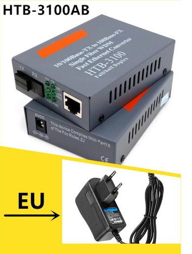
We will be needing something to convert between UTP and fiber: two fiber modems, one at each end. As usual the Chinese have something cheap and cheerful (only RM25/USD5) called a media converter: the HTB-3100.

The HTB-3100A and HTB-3100B are sometimes sold as a matched  pair

Now this being a Chinese no-name box, be careful to look for a media converter that has only one fiber SC UPC port. The picture above shows two (marked TX and RX) but only the TX port can be uncovered. If you, like me, happen to buy the dual-port box by mistake you will need to lay 2 fiber cables for every copper UTP connection. You want to look for WDM (Wavelength Division Multiplexing). To carry 2 channels in one fiber, it transmits in one wavelength, 1550nm and receives at another, 1310nm. That is Type A. Type B is just the reverse, transmitting at 1310nm and receiving at 1550nm. You will be needing one unit of each type. They are often sold in matched pairs.

Both the single fiber and dual fiber media converters might be labelled as Half/Full Duplex. My guess is this refers to the UTP (ie RJ45 or copper) end. These days most CAT5 or CAT6 copper LAN cables come with both TX and RX pairs, and Half Duplex might be when Ethernet is negotiated down to CSMA/CD. 

Last but not least there is the complex matter of cutting, splicing and terminating your fiber optic cable. Years ago, it took expensive equipment, highly-trained operators and extremely clean conditions, which are sometimes difficult to do on-site. But for now there is and end-run, a workaround. Again from the Chinese. You can buy the cables already terminated for very low prices. Like RM36 for 50m. That is just USD9.

Pre-terminated outdoor single mode fiber cable.

Some suppliers will do it to a custom length. Just make sure the connector is SC UPC (it is easy to specify the incompatible SC APC or LC connectors). Now I had coax 10Base2 concealed LAN wiring installed in my house (yes, yes I am a dinosaur), so it was an easy matter to rip it out of the conduits and install the smaller fiber cable in it place.

The aim is to replace your long copper cable runs with fiber. One benefit is if the cable run is over 100m you do not need to install the repeaters (ie LAN switches) that UTP Ethernet needs. If you add in the cost of the power wiring, enclosures, the savings quickly pile up.

The aim is to replace long copper LAN cable runs with fiber (in red)


It worked so well I ran another 100m fiber cable outdoors to my home office so I can share the broadband. The system has been in place through several violent thunderstorms and one fallen tree and did not miss a beat.

If you live in Malaysia, you are in luck, for Talikom Malaysia, the telecoms monopoly mostly uses sub-contractors to install your FTTH fiber cable. For a very reasonable fee, not exceeding the cost of a roll of fiber cable, they can be persuaded to do your internal house fiber cabling. In my case it was money well spent for much of the work involved climbing onto the roof. A huge advantage is they will splice and terminate your fiber cable using proper equipment, resulting in a very good connection.

The only thing left would be an inexpensive way to cut, join and terminate a fiber cable myself. But that is for another post.

Happy Trails. 


Thursday, 17 December 2020

RESTful IoT with privacy & security: How to set up a Debian HTTPS Server


"It is quiet here and restful, and the air is delicious. There are gardens everywhere and police spies lie in the bushes ... " - Maxim Gorky

It is very tempting to use the ubiquitous HTTP web protocol for IoT. It is easy to test, and lets you operate your IoT from smartphones, tablets, desktops and even a computer program. Such a setup is called RESTful. It simply means your IoT device speaks the language of the web browser and web server. 


So we rush ahead with our RESTful API, and the IoT device is soon working and indispensable. Pretty soon we realize we need security and privacy: it won't do to have a hacker open the voice-controlled garage door ...

Our first line of defense is our WiFi password. It is reasonable to assume those living in the house should have access to WiFi and IoT. But what if we had guests or lodgers? Changing WiFi passwords can be a real bear, especially if you have 20-odd IoT devices. In fact it makes sense to localize the changes to a dedicated IoT server. RESTful, naturally.  

We will be needing some form of authentication: account names and passwords should do for now. Next we will need a reasonable amount of privacy, i.e., encryption so that someone else should not be able to lift the IoT password off the WiFi. That means HTTPS, or HTTP with SSL.

We start by implementing HTTPS server on a Linux system. The ESP8266 is known to be a little wobbly running HTTPS. ESP32 is better, but we can do without the complication for now. The traditional way is to use Apache. There are other, easier ways (like nginx, nodejs and even python) but Apache lets you run multiple servers right off the bat. This means you can keep your bad old HTTP server, add another HTTPS server on top of that and lets you support both your HTTP and HTTPS IoT devices.

From a bog-standard Debian (mine is a Beaglebone on eMMC), do the usual:

# apt-get update

# apt-get upgrade

Next, get Apache:

# apt install apache2

And while you are at it, you might as well make sure you have ssh. I got my DNS from duckdns.

Apache should come up complete with the stock webpage at http://localhost. Put your webserver files at /var/www/html/

To access the webserver from outside your WiFi access point, you will need a DNS server, but once you get it organized, a bog standard browser will display a warning before it will display your home page:


That means you need SSL, which usually costs money. You can opt for a self-signed certificate but this will produce a warning with most browsers. You then elect to disregard the warning and proceed, but this is a real problem if you are trying to sell the IoT device.

One way out is to get a 90-day certificate free from sslforfree. You just have to register, input your domain name and prove that you have access to the webserver, usually by uploading an sslforfree file to it. After it checks out the certificates can be downloaded. sslforfree links to a youtube video describing the process.

Do check out the video. I will simply list the differences relevant to a Debian installation. In Debian it is a simple:

# a2enmod ssl
Considering dependency setenvif for ssl:
Module setenvif already enabled
Considering dependency mime for ssl:
Module mime already enabled
Considering dependency socache_shmcb for ssl:
Enabling module socache_shmcb.
Enabling module ssl.
See /usr/share/doc/apache2/README.Debian.gz on how to configure SSL and create s
elf-signed certificates.
To activate the new configuration, you need to run:
  systemctl restart apache2

I now need a configuration file for my HTTPS (or SSL) webserver. There is a template in Debian:

# cp /etc/apache2/sites-available/default-ssl.conf /etc/apache2/sites-available/secure.cmheong.duckdns.org.conf

secure.cmheong.duckdns.org being the domain name of my new HTTPS server. The parameters for the new server are put in:

# cat /etc/apache2/sites-available/secure.cmheong.duckdns.org.conf | head -n 16
<IfModule mod_ssl.c>
        <VirtualHost _default_:443>
                ServerName secure.cmheong.duckdns.org
                ServerAlias www.secure.cmheong.duckdns.org
                ServerAdmin webmaster@secure.cmheong.duckdns.org

                DocumentRoot /var/www/html

                # Available loglevels: trace8, ..., trace1, debug, info, notice, warn,
                # error, crit, alert, emerg.
                # It is also possible to configure the loglevel for particular
                # modules, e.g.
                #LogLevel info ssl:warn

                ErrorLog ${APACHE_LOG_DIR}/secure.cmheong.error.log
                CustomLog ${APACHE_LOG_DIR}/secure.cmheong.access.log combined

You then check your configuration and do not proceed further until this passes:

# apachectl configtest
Syntax OK

Make sure your webserver is now accessible from the Internet. Usually this means setting up Port Forwarding in your gateway to forward all port 443 traffic to your server IP address.

# systemctl restart apache2

You will then need to prepare for the sslforfree test of webserver and domain name ownership:

# mkdir /var/www/html/.well-known
# mkdir /var/www/html/.well-known/pki-validation

Register with sslforfree, download the challenge file they provided and put it in the new directory. This is where the Debian ssh installation comes in handy. 

If the sslforfree challenge succeeds, then the certificates and private key will be generated as a zip file.

# unzip secure.cmheong.duckdns.org.zip
Archive:  secure.cmheong.duckdns.org.zip
 extracting: certificate.crt
 extracting: ca_bundle.crt
 extracting: private.key

You then move them to their final secure directories:
# cp -v ./sslforfree/*.crt  /etc/ssl/certs
'./sslforfree/ca_bundle.crt' -> 'certs/ca_bundle.crt'
'./sslforfree/certificate.crt' -> 'certs/certificate.crt'

# cp  ./sslforfree/private.key  /etc/ssl/private/private.key

Remember to delete the ./sslforfree directory. If you want to put the certificates in a different place you will need to update the site config file accordingly:

# cat /etc/apache2/sites-available/secure.cmheong.duckdns.org.conf | grep -i SSLCerti
                #   SSLCertificateFile directive is needed.
                #SSLCertificateFile     /etc/ssl/certs/ssl-cert-snakeoil.pem
                #SSLCertificateKeyFile /etc/ssl/private/ssl-cert-snakeoil.key
                SSLCertificateFile      /etc/ssl/certs/certificate.crt
                SSLCertificateKeyFile /etc/ssl/private/private.key
                SSLCertificateChainFile /etc/ssl/certs/ca_bundle.crt

As usual test the Apache configuration:

# apachectl configtest

And then restart Apache:

# systemctl restart apache2

The just aim your Chrome browser at https://www.yoursecureserver.com. If it worked you get something like this:


Now the traffic to and from the IoT RESTful server is encrypted. Note the sslforfree certificates expire in 90 days, but you are free to generate a new set. They will even email you a reminder. 

There you have it: a secure Internet-facing RESTful IoT server.

Happy Trails.

Sunday, 9 August 2020

If at first you don't succeed, try try again: Flashing an old Beaglebone Black eMMC


2019 Hugo Award for Best Novelette: Zen Cho

Back in 2016 I bought a few Beaglebone Blacks, but did not get round to using them. I guess they were superseded by the later-model Raspberry Pi's. 


Beaglebone Black


The Pi has always been less reliable than the Beagleboard or Beaglebone. Broadcom USB subsystem was especially flaky and since the Pi USB bus handled both disk IO as well as Ethernet, you are often SOL as Broadcom is not really reknown for fixing things. Little things like industrial temperature rating of 85 degrees Celsius. And having to run Linux from sdcards, which are certain to wear out. Even worse the full-size sdcard sockets fail after a few years. Luckily the later Pi models use microsd sockets, but I am still stuck with a bunch of Pi Model Bs and their flaky sdcards.

The Pi had irresistible things going for it. It was way cheaper, had more addon modules (ie 'hats'), and best of all, it had Debian. There was no longer the month-long struggle to get Angstrom Linux to run properly. Yet those niggling problems ...

Getting my Beaglebone Black running was unexpectedly painless. I plugged it into my laptop USB port and it was running. It came up as /dev/ttyACM0 a serial port. No problem, all I needed was minicom, and the default settings of 115200 baud, 8 bits, 1 stop, no parity.


Default account is 'debian' and password 'tempwd'. There is no root password. I did not have to struggle with Angstrom. In fact I forgot to put in the sdcard. That meant it loaded from on-board mass storage. And it was Debian!

root@beaglebone:~# cat /etc/dogtag

BeagleBoard.org Debian Image 2015-03-01

Turned out the onboard memory was eMMC, still flash memory, but in IC form without those dreaded sockets. Memory is 512MB and there is no built-in WiFi; that would come only in the Beaglebone Black Wireless.

From bottom left: USB Master socket, microsd  and the elusive User-boot button


First order of business with Debian is to get it up to date. I connected it via copper LAN to my ADSL modem where it found the Internet on its own. But 'apt-get update' had errors, even though it technically did not fail:

root@beaglebone:~# apt-get update

W: Failed to fetch http://ftp.us.debian.org/debian/dists/wheezy/contrib/binary-a
rmhf/Packages  404  Not Found [IP: 64.50.233.100 80]

W: Failed to fetch http://ftp.us.debian.org/debian/dists/wheezy/non-free/binary-
armhf/Packages  404  Not Found [IP: 64.50.233.100 80]

W: Failed to fetch http://ftp.us.debian.org/debian/dists/wheezy-updates/main/bin
ary-armhf/Packages  404  Not Found [IP: 64.50.233.100 80]

'apt-get upgrade' finished OK:
root@beaglebone:/home/debian# apt-get upgrade

But the version was wheezy, and really old. Not to worry, I reached for the latest images, and downloaded AM3358 Debian 9.12 2020-04-06 4GB SD ImgTec. It only needed a tiny (4GB!) microsd card, and:

$xzcat bone-debian-10.3-iot-armhf-2020-04-06-4gb.img.xz | sudo dd of=/dev/sdc
7372800+0 records in
7372800+0 records out
3774873600 bytes (3.8 GB, 3.5 GiB) copied, 3001 s, 1.3 MB/s

But it did not boot from the microsd, and instead after an hour or so booted from eMMC. Time to Read the Manual. The manual is no fluffy faux-friendly 'Getting Started' guide; it reads like a datasheet with schematics in glorious abundance.

There is mention of a 'Boot button', where if held down and the beaglebone is power-cycled it will force a boot from sdcard. But it did not work - and eventually always reverted to the old eMMC wheezy Debian.

After wasting a couple of days ruling out a hardware malfunction, the problem had to be the Debian image. One hint was that Debian Image 2015-03-01 would not mount  Debian 2020-04-06. That would point to an ext3 filesystem incompatibility. The existing eMMC Debian code would be needed to mount and boot the new Debian before flashing can commence.

And yet all this  has been solved before; one compromise is to use an fossil filesystem (like FAT16) just for booting, and indeed Debian 015-03-01 had such a partition but not Debian 2020-04-06. Usually SoCs have separate bootrom to prevent bricking incidents like this (like its close cousin the Beaglebone White), but this is easy enough to test.

beaglebard.org maintains a complete archive of old images, and hoping for an intermediate Debian that will be compatible with both, I picked Debian 2016-12-09. Then it s a simple matter of:

$xzcat bone-debian-8.6-iot-armhf-2016-12-09-4gb.img.xz > /dev/sdc

And it booted from microsd, just like that.

root@beaglebone:~# cat /proc/version
Linux version 4.4.36-ti-r72 (root@a2-imx6q-wandboard-2gb) (gcc version 4.9.2 (Debian 4.9.2-10) ) #1 SMP Wed Dec 7 22:29:53 UTC 2016

You need to prepare the new image for flashing. Just find the file /boot/uEnv.txt and uncomment the last line:

cmdline=init=/opt/scripts/tools/eMMC/init-eMMC-flasher-v3.sh

To flash the eMMC, I added the 5V power cable, and powered off. Then with the microsd still in, held down 'User boot'  button and powered back on. This worked right off the bat; the blinkenlights did an impression of Pong, and when finished, all lit up, then shut down.

On powering up, and removing the microsd, I get:

root@beaglebone:~# cat /etc/dogtag
BeagleBoard.org Debian Image 2016-12-09

Our imugi is not yet a dragon, but this is clearly The Way. The trusty sdcard is then repurposed with:

$xzcat bone-debian-10.3-iot-armhf-2020-04-06-4gb.img.xz | sudo dd of=/dev/sdc

And now it booted off the microsd. Now all I need to do is to repeat the eMMC flashing process with the latest Debian Image, 2020-04-06. As a precaution I first upgraded without incident:

root@beaglebone:~# apt-get update
root@beaglebone:~# apt-get upgrade

Changed the default passwords did the usual sysadmin stuff. The eMMC flash went without incident, and unlike Zen Cho's Byam, my Beaglebone Black did not turn back but transformed its eMMC to Debian 2020-04-06.

Happy Trails.

Sunday, 19 July 2020

AS3935: The Next Generation Episode 2

Hors de combat: AMS1117-3.3 LDO with crater and ejecta

In Episode 1, I isolated the modem ADSL disconnect relay module, and this setup survived about three months of storms, until this week. The system worked pretty well: the remote AS3935 disconnected the ADSL line from the modem a good 20 minutes earlier, so the problem area was limited to just the relay board. Instead of blowing everything up like my first rig.


Setup at time of strikes


Relay board with ESP-01S dismounted. No obvious burn marks this time.

However the ADSL line is still connected to the relay board pins, a lightning strike first took out the 12V to 5V DC-DC buck converter that served as the power module for the relay board. This caused the output to short-circuit to the input: 12V from the battery now appeared at the relay board power input.

Relay board after the second strike. Note the insulation tape over the relay pins

Now the AMS1117-3.3 LDO power regulator in the relay board is rated for 15V and while it crashed the ESP8266 CPU it probably  did not kill it. It did cause the 5V relays to run really hot. This set it up for the second close strike, just minutes later, which blew a neat little hole in the AMS1117-3.3.

It is very impressive what damage lightning can do. But there seems to be progress. The AS3935 lightning detector allowed an early modem disconnect, which probably saved the modem. And this time round there seems to be a lot less damage, probably because the lightning could not find an easy path to earth. The earlier 'disconnect' signal from the AS3935 module caused a second relay board to disconnect the battery charger from the mains. At the time of the second strike the system had been running off the 12V battery.

Since the strike also killed the 12V-5V DC buck converter powering the relay board from the battery, perhaps disconnecting the ADSL relay board from the buck connector might improve things. It does not really need to be powered up: I can use the relay 'Normally Open' pins to ensure the ADSL stayed disconnected. The relay board's 5V is really close to the ADSL pins as it needed to power the relay coil.

And I can make things a little more robust by using a 12V relay board to disconnect the ADSL relay board and to monitor for the storm's passing so that the modem can be reconnected when it is safe.

Diymore 4-channel WiFi Relay board with serial interface
And as a bonus the module PCB designer has helpfully cut a slot around the vulnerable relay output COMMON pin.

Note the 'U'-shaped slots cut around the relay COMMON pin

The power regulator is still an AMS1117-3.3 but now there is an added 78M05 linear regulator in series. This raises the maximum input voltage (ie the tolerance to surges) to 35V, from the AMS1117-3.5's 15V. Hopefully this is enough, but we are never really sure until the next lightning strike demolishes it. The relay coils are still exposed to the full weight of the surges but they are relatively tougher devices.

The setup is now thus:

System block diagram: the other 2 relays in the 4-channel module are used to disconnect the battery charger from the mains

Next Generation Episode 2 build: from top: 2-channel ADSL relay module, ADSL modem and 4-channel power disconnect module

Thus fortified, we await the next thunderstorm. Indeed I welcome the strikes, for it is looking like my 30-year struggle with lightning strikes may be coming to a close: fiber-optic broadband network has reached my front gate, and the service provider salesman will not be long after. Just when I felt like I am winning.

Fiber at the gates: the end for copper-based ADSL broadband is nigh


What is Ahab without his Moby Dick? Come, lightning and welcome. 


Happy Trails.

Ahab and his whale