|
| Your pins are feeling heavy ... you shall enter a Deep Sleep ... |
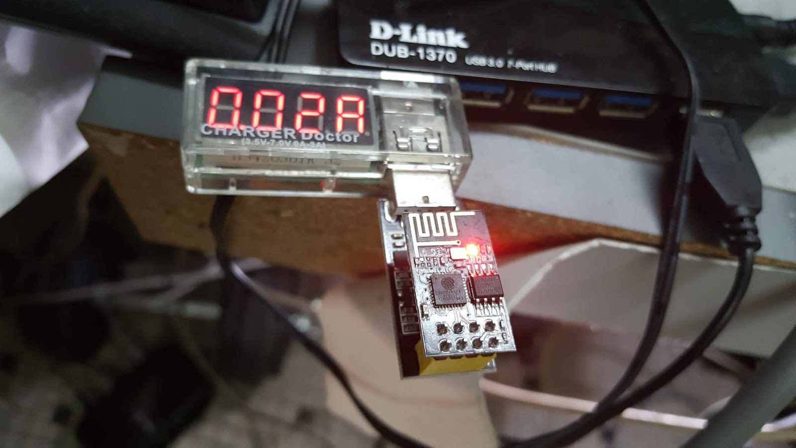
The ESP8266 is not exactly a low-power device and you really feel it when you are running it from a battery. An ESP-01S can draw up to 70mA when connected to its Access Point. A 3000mAh power bank will not last 2 days at that rate. Even doing nothing, the ESP-01S in program mode draws 20mA
 |
| Idle ESP-01S draws 20mA |
Putting it to sleep can reduce the current to less than 1mA as this excellent link from randomnerd shows.. Now we're talking! but this usually means the bare board - randomnerd even removed the power LED to save those extra mA. Most applications require a little more peripherals so even if my current draw is 7mA my 3000mAh power bank will now last 18 days instead of 2, which is good enough for a start.
randomnerd's writeup is pretty much complete - I will not repeat his work here. The first test using the ESP-12E was done in less than an hour. I only had to connect D0 to RST.
 |
| ESP-12E all wired up for deep sleep. Notice the active current draw of 60mA |
I used a cheap little USB ammeter for no other reason than it was handy and convenient, but it had a resolution of only 10mA. The ESP-12E current draw dropped from 60mA to 'zero' (ie less than 10mA) in deep sleep.
Thus encouraged, I soldered the wire required for the ESP-01S. But unlike randomnerd, rather than entering deep sleep the ESP-01S continually rebooted. This doesn't mean randomnerd gave bad advice. As usual with these cheap boards, your milage may vary.
 |
| Wiring D0/GPIO16 directly to ESP-01S RST pin did not work |
The answer
here sounded convincing: D0/GPIO16 floats high when in deep sleep and this can trigger RST which wakes up the ESP8266 who then runs its program and goes back to sleep and so on. The recommendation was for a 470Ohm resistor in series. I happened to have a 560Ohm one so in it goes:
 |
| Adding a 560-Ohm resistor in series worked |
And work it did. I like the ESP-12E well enough but the ESP-01S is just so easy to package. Time to put it to good use.
And immediately found a gotcha- when it wakes from deep sleep it is equivalent to a hard reset. This means it no longer has its volatile memory (RAM). This makes things a little tricky if the ESP-01S had to drive an output like a relay or a transistor.
Now it will be still handy as an IoT input device running on battery. It wakes up, say every 5 minutes, connect to the access point, takes a reading of its sensor, say the room temperature, or a door magnetic switch and publish it to an MQTT server. The server acts as its non-volatile memory and with a little luck we might be even be able to finesse an IoT output by reading the MQTT subscription and re-initializing its output before the load realizes it. This will depend on whether the relay board is able to hold its output with the ESP-01S in deep sleep.
So in a fit of optimism, fired up by success so far, I got out a
1-channel relay PCB.
 |
| Notice the maximum current draw is 130mA with the ESP-01S awake and the relay on |
The current draw of the ESP-01S with the relay on is 130mA. Now it does not make complete sense to drive an IoT relay output from a battery. Often the load will need power as well and may may draw precious mA from the battery.
The program is:
#include <ESP8266WiFi.h>

#include "RemoteDebug.h" // 2019-04-08 https://github.com/JoaoLopesF/RemoteDebug

RemoteDebug Debug;

#define HOST_NAME "esp01s-1relay"


const char* ssid = "YourAP"; // For testing in study

const char* password = "YourPassword";


IPAddress staticIP(12,34,56,78); // for testing in study only

IPAddress gateway(12,34,56,1); // for testing in study only

IPAddress subnet(255,255,255,0);


// Create an instance of the server

// specify the port to listen on as an argument

WiFiServer server(8080);


static int count = 0;

void setup() {

  Serial.begin(115200);

  delay(10); // 2018-10-08

  Serial.setTimeout(2000); // 2019-04-08

  pinMode(0, OUTPUT); // 2018-10-25 set gpio to o/p

  digitalWrite(0, 0); // Default to 'off' state to save power. relay board starts up with relay 'on'

  delay(10);


  // Connect to WiFi network

  Serial.println();

  Serial.println();

  Serial.print("Connecting to ");

  Serial.println(ssid);


  WiFi.mode(WIFI_OFF); //workaround 2018-10-08

  WiFi.mode(WIFI_STA);

  WiFi.begin(ssid, password);

  WiFi.config(staticIP, gateway, subnet); // Static IP. Not required for dhcp


  while (WiFi.status() != WL_CONNECTED) {

    delay(1000);

    Serial.print(".");

    count++;

    if (count >= 300) // 5 minutes==300s

    {

      count = 0;

      Serial.println("setup() giving up trying to connect to AP! waiting for WDT reset ... see you in 5min");

      delay(20);

      while (1)

      {}

    }

  }


  Serial.println("");

  Serial.println("WiFi connected");


  String hostNameWifi = HOST_NAME; // 2019-04-08 for remote debug

  hostNameWifi.concat(".local");

  WiFi.hostname(hostNameWifi);

  Debug.begin(HOST_NAME); // Initialize the WiFi server

  Debug.setResetCmdEnabled(true); // Enable the reset command

  Debug.showProfiler(true); // Profiler (Good to measure times, to optimize codes)

  Debug.showColors(true); // Colors


  // Start the server

  server.begin();

  Serial.println("Server started");

  debugI("Starting http server ...");

  delay(50); // 2018-10-25


  // Print the IP address

  Serial.println(WiFi.localIP());

  Debug.handle();

  yield();

}


static int dots = 0;

static int val = 0; // 2018-10-25

static int commas = 0;


void loop() {

  // 2019-02-27 Check for broken wifi links

  if (WiFi.status() != WL_CONNECTED) {

    delay(10);

    // Connect to WiFi network

    Serial.println();

    delay(10);

    Serial.print("Reconnecting WiFi ");

    debugI("Reconnecting WiFi ");

    delay(10);

    WiFi.mode(WIFI_OFF); // 2018-10-09 workaround

    WiFi.mode(WIFI_STA);

    WiFi.begin(ssid, password);


    while (WiFi.status() != WL_CONNECTED) {

      Serial.print("x");

      debugI("x");

      delay(500);

      dots++;

      if (dots >= 1000)

      {

        dots = 0;

        Serial.println("Giving up! Waiting for WDT reset ...");

        debugI("Giving up! Waiting for WDT reset ...");

        delay(20);

        yield();

        delay(20);

        while (1)

        {}

      }

      yield();

    }

    Serial.println("");

    delay(10);

    Serial.println("WiFi reconnected");

    debugI("WiFi reconnected");


    // Start the server

    server.begin();

    Serial.println("Server restarted");

    debugI("Server restarted");

    delay(10);

    // Print the IP address

    Serial.print("IP address: ");

    delay(10);

    Serial.println(WiFi.localIP());

    delay(10);

    Debug.handle();

  }


  // Check if a client has connected

  WiFiClient client = server.available();

  if (!client) {

    delay (10); // 2018-10-25

    //Serial.println("server not available!");

    // Serial.print("."); // no harm but too many dots

    delay(20);

    Debug.handle();

    return; // 2019-02-27 missing return

  }


  // Wait until the client sends some data

  Serial.println("new client");

  debugI("new client");

  while(!client.available()){

    delay(10); // 2019-02-28

    //Serial.println("client not available!");

    Serial.print(",");

    debugI(",");

   if (commas++ > 5) { // 2019-02-28

      commas = 0;

      Serial.println("Terminating client connecting without reading");

      debugI("Terminating client connecting without reading");

      delay(20);

      client.stop();

      Debug.handle();

      yield();

      return;

    }

    Debug.handle();

  }


  // Read the first line of the request

  String req = client.readStringUntil('\r');

  Serial.println(req);

  client.flush();


  // Match the request

  String s = "";

  // Prepare the response

  if (req.indexOf("/gpio/0") != -1) {

    val = 0;

    // Set GPIO2 according to the request

    digitalWrite(0, val);


    s = "HTTP/1.1 200 OK\r\nContent-Type: text/html\r\n\r\n<!DOCTYPE HTML>\r\n<html>\r\nRelay is now ";

    s += (val)?"on":"off";

    s += "</html>\n";

    debugI("relay off");

  }

  else if (req.indexOf("/gpio/1") != -1) {

    val = 1;

    // Set GPIO2 according to the request

    digitalWrite(0, val);


    s = "HTTP/1.1 200 OK\r\nContent-Type: text/html\r\n\r\n<!DOCTYPE HTML>\r\n<html>\r\nRelay is now ";

    s += (val)?"on":"off";

    s += "</html>\n";

    debugI("relay on");

  }

  else if (req.indexOf("/sleep/") != -1) {

    int value_index = req.indexOf("/sleep/");    // Here you get the index to split the response string right where it says "value"

    String value_string = req.substring(value_index);

    String value = value_string.substring(7, value_string.indexOf("\r"));   // Here you ignore the first nine characters of the substring ("-v-a-l-u-e-"-: ), then get the value, then ignore the rest of the string after the comma.

    Serial.println(value);

    s = "HTTP/1.1 200 OK\r\nContent-Type: text/html\r\n\r\n<!DOCTYPE HTML>\r\n<html>\r\nValue is now ";

    s += value;

    s += "</html>\n";

    val = value.toInt();

    debugI("Sleeping for %ds", val);

    //char valueless[80];

    //value.toCharArray(valueless, 80);

    //debugI("Sleeping for %s\n", valueless);

  }

  else if (req.indexOf("/index.html") != -1) {

    s = "HTTP/1.1 200 OK\r\nContent-Type: text/html\r\n\r\n<!DOCTYPE HTML>\r\n<html>\r\nRelay is ";

    s += (val)?"on":"off";

    s += "</html>\n";

    debugI("relay state is %d\n", val);

  }

  else {

    Serial.println("invalid request");

    s = "HTTP/1.1 200 OK\r\nContent-Type: text/html\r\n\r\n<!DOCTYPE HTML>\r\n<html>\r\nInvalid request</html>\n";

    debugI("invalid request");

  }

  Debug.handle();

  yield();

  client.flush();


  // Send the response to the client

  client.print(s);

  delay(10);

  client.stop(); // 2019-02-27

  Serial.println("Client disonnected");

  delay(10);

  // The client will actually be disconnected

  // when the function returns and 'client' object is detroyed

  if (val>1) {

    debugI("Sleeping for %ds", val);

    Serial.print("Sleeping for ");

    Serial.println(val);

    Debug.handle();

    delay(20);

    ESP.deepSleep(val); // 2019-04-08

  }

}
I have included
Joao Lopes' Remote Debug code, as once mounted on the relay board it was difficult to get debug messages. You just do:
telnet 12.34.56.78
The program starts up with the relay off and initially draws 60mA. When the relay is turned on the system draws another 60mA. The deep sleep function is
ESP.deepSleep(val) . On calling it, the current draw went from 120mA to 60mA. To turn on the relay, you use a browser or the lynx command:
$lynx -read_timeout=5 -dump -cmd_script=./lynx_script http://12.34.56.78:8080/gpio/1
Relay is now on
To sleep 30 seconds you specify the time in microseconds:
$lynx -read_timeout=5 -dump -cmd_script=./IoT/lynx_script http://12.34.56.78:8080/sleep/30000000
Value is now 30000000 HTTP/1.0
The relay board proved unable to hold its last state when the ESP-01S goes into deep sleep. When deepSleep() is called the relay turns on. This resulted in the same current draw of 60mA. The 60mA saved by the deep sleep is taken up by the relay coil current. But dropping the relay state on deep sleep is a deal breaker for most applications.
Time to try the 2-channel relay. You can get it on
ebay here. It has its own microprocessor, which should mean it can hold its state without the ESP-01S. The ESP-01S turns on the relays using the serial port. In the program you just replace code like:
digitalWrite(0, val);
with
//Hex command to send to serial for close relay
byte relON[] = {0xA0, 0x01, 0x01, 0xA2};
//Hex command to send to serial for open relay
byte relOFF[] = {0xA0, 0x01, 0x00, 0xA1};
//Hex command to send to serial for close relay
byte rel2ON[] = {0xA0, 0x02, 0x01, 0xA3};
//Hex command to send to serial for open relay
byte rel2OFF[] = {0xA0, 0x02, 0x00, 0xA2};
Serial.write (relON, sizeof(relON));
And sure enough it works. With the ESP-01S running and the relays off, it draws 70mA, about the same as the 1-channel relay board. With the ESP-01S in sleep mode it draws less than 10mA.
 |
| Dual Relay PCB with uP serial control. Note less than 10mA current draw in deep sleep |
With everything running and both relays on, the current draw is 190mA. With ESP-01S now put to deep sleep, the relays retain their state and the system draws 120mA. More importantly when it wakes up, the relay state is still retained (although the ESP-01S will not remember this and has to subscribe to MQTT to find out).
 |
| Maximum power: 190mA with both relay and ESP-01S on |
This is actually the ideal setup for my
Google Voice activated IoT Autogate. The original version used 230Vac for power. Now I can use the autogate 12V backup battery. In the event of a power cut (happens a lot in my house but that is another story), I was afraid the IoT would drain the battery. Now I can simply put it to sleep. To use voice activation during a power cut, I simply set the sleep timer for 5 minutes. The command would be saved in the MQTT server feed and would be read by the ESP-01S when it wakes up. Even better, the autogate uses command pulses, so the relays are never active for more than 1 second.
There you have it: doing good while in deep sleep. Just goes to show in electronics, sometimes you can have your cake and eat it. Happy Trails.