 |
| Volkswagen Beetle (Bug) Type 1. Photo by Vwexport1300 |
The fuel gauge in my 1969 VW Beetle (Bug) Type 1 failed. The needle kept indicating 'Full' no matter how much petrol I have in the tank. And the workshop said that a new meter assembly will need weeks to arrive and I really did not fancy driving with a jerrycan of fuel in case I ran out.
Now I know very little about cars; my thing is electronics and software. However, from 1968, the Beetle fuel gauge system is electrical (aha!), and armed with Speedy Jim's excellent webpage on Beetle/Bug fuel gauges, I got to work.
 |
| VW Beetle Type 1 fuel gauge schematic by Speedy Jim |
The schematic shows a voltage regulator (quaintly called a 'vibrator') powering the meter in series with a potentiometer controlled by a float. The potentiometer and float ('sender') lived inside the fuel tank
 |
| VW Beetle electrical type fuel sender |
The fuel tank is easily accessible for testing - just pop the front bonnet.
 |
| Beetle/Bug fuel tank. Sender is in front middle of the fuel tank |
The output of the potentiometer (sorry - sender) connects directly to the gauge and is easily disconnected.
 |
| Fuel Gauge Sender Connector |
The fuel gauge is built into the speedometer, at the top middle. This explains the high replacement cost.
 |
| VW Beetle Speedometer: fuel gauge is top middle |
The cabling is at the back, and luckily the wires are also easily accessible.
 |
| Speedometer, back view. The regulator is riding on the meter's shoulder, on the left |
 |
| Top view of mounted regulator. Photo by wagohn |
Speedy Jim has a cut-out view of the fuel gauge; the current heats up a bimetallic strip and directly drives the needle. Far out! No magnet, no electrical coil. This is so cool.
 |
| Picture by Speedy Jim |
The regulator when dismounted looks like this, and is a little reminiscent of a 3-terminal regulator:
 |
| VW Beetle/Bug Fuel Gauge Regulator |
 |
| 3-terminal regulator: LM7812 in TO-220 package |
It is time to test. A quick check with the multimeter showed that my sender terminal is reading 5V with the ignition on. With the sensor disconnected the wire from the gauge reads 10.8V. With the ignition off the sender reads 18 Ohms. Speedy Jim has it as 73 Ohms empty and 10 Ohms full. After a couple of days running the sender read 28 Ohms. So the sender seems to be working. This is further confirmed by parking the Beetle uphill and then downhill to move the needle some more.
Next is the test for the fuel gauge. Speedy Jim (thanks, Jim!) has detailed instructions. With the wire disconnected (do not let it short to the VW body!), the gauge read empty. Short the wire to the car body and now it reads 'Full' as before.
This leaves the voltage regulator as the prime suspect. My guess was it shorted out its input to its output, and is applying the full 12V input voltage to the gauge bimetallic strip. Hence the constant 'Full' reading. Happens often enough in 3-terminal regulators.
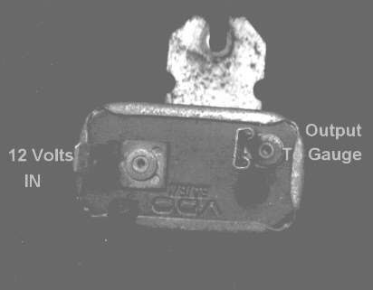 |
| Regulator pinout: photo by Speedy Jim |
Now rather than fumble around with my gauge, Speedy Jim has very handy pictures of a disassembled regulator.
 |
| Photo by Speedy Jim |
There are no semiconductors in the regulator! It is not even solid-state: it is all metallic. The redoubtable Speedy Jim is worth quoting in full:
"... 12V from the battery heats up the heater element and warms the strip. The thermal mass is small and the strip responds very rapidly. As soon as it begins to move, the strip causes the contact points to open. This breaks the circuit and the current ceases. Now, the strip begins to cool off and bends back to its original shape, closing the contact. This repeats, over and over. The result is a series of pulses, each with a voltage of 12V. When the pulses are fed to the gauge, the heater element in the gauge averages the pulses out.
 |
| Diagram by Speedy Jim |
The diagram leaves no doubt. Far from a humble LM7812, this is a switched-mode power supply. The diagram show a pulse-width modulated (PWM) output at a frequency of 3Hz and duty cycle of 33%. And all this using just metal. It is as if I decapped a SMPS controller IC like the MC34060 and all I found was solder and wire! Compare this to a typical SMPS:
 |
| Solid-state SMPS |
And you cannot argue with the reliability: I got the Beetle in 1992 and that regulator must have lasted 30 years of steady use, in a harsh environment with lots of vibration and shock. I would have been pleased if a solid-state regulator lasted half as long. Since it is a 1969 model there is a good chance it might have lasted over 50 years.
Now since the switching rate is only 3Hz, it should be visible if connected to a light. Speedy Jim used a light bulb, but these days there are very cheap 12V LED modules, especially if you cut one off a strip light.
 |
| 12V LED module: just connect directly to the regulator |
I unhooked the sender wire and connected it to the LED module. It lit up but did not blink, so there is no switching by the bimetallic strip in the regulator. I ordered a cheap China part for RM28 (USD4) . This would just be a rudimentary solid-state regulator with just a zener diode and a limiting resistor.
Now I do not recommend connecting anything electrical to the fuel tank much less 12V from a car battery that can potentially deliver 200A, so extreme care is necessary, in particular when you connect up the wires. Note that the current from the regulator is from the 12V car battery and is being limited by the coil in the fuel gauge so we will use that as the power source. Still the following section delivers a 12V PVM signal into the fuel tank potentiometer (as well as the fuel gauge) and there is always a risk of sparks, especially if you move the fuel tank.
But it was still a good 10 days before it arrived, and in the meantime it would be nice to actually produce those PWM pulses if only to see history in action once more ...
 |
| L293D Motor Shield for NodeMCU ESP-12E V2 |
I had been working on a WiFi-controlled L293D Motor Shield for ESP-12E NodeMCU and it produces 12V PWM pulses suitable for driving DC motors as well as LED lighting. It runs an Arduino sketch, and you can get a copy from github.
The key change is to the PWM frequency:
analogWriteFreq(3); /* Arduino v1.8.5 only */
Note the current Arduino reference says that the minimum value is now 100Hz. However I am on an old version, 1.8.5 and I could dial down the PWM frequency right down to 3Hz, so your mileage may vary.
I disconnected the regulator from the sender, and wired up the motor shield thus:
 |
| Pinout for VW Fuel Gauge Regulator PWM |
The LED module is used to observe the PWM blink rate. You enter your WiFi access point SSID and password, recompile and download the program into the ESP-12E V2, usually via the microUSB port.
You will want to test youe setup driving 12V LEDs instead of the sender. Since you want to connect to the fuel tank at the last possible moment. I set up everything, including the phone browser before I did so. In particular you do not want to accidentally reverse the polarity to the sender, either by miswiring or by using the program's motor reverse command. An LED indicator is better than a filament bulb here.
Once the program starts your 12V led module will start blinking at 3Hz. To send a signal to the fuel gauge, you use a browser (I used Google Chrome on my Android smartphone) and type in:
http://12.34.56.78:8080/pwm1/33
And the fuel gauge immediately started registering the petrol level in the tank. This is because the L293D produces a 3Hz pulsetrain at 33% duty cycle, just like Speedy Jim said.
And you can produce a zero fuel reading by:
http://12.34.56.78:8080/pwm1/0
A full tank reading is
http://12.34.56.78:8080/pwm1/100
And not wanting to push my luck, I took down the setup as soon as I could. 10 days after, the new regulator arrived and the VW fuel gauge was fixed. I kept the faulty regulator: it is a reminder that SMPS is a lot older than solid-state electronics.
 |
| Root cause: the heater element appears to have disintegrated so the regulator is stuck in the 'On' position and failing to switch off |
Happy Trails.


