Sunday 17 January 2021

One rail to rule them all: Powering the NodeMCU ESP-12E with 12V


NodeMCU Motor Shield with ESP-12E Devkit and 6.8V 1W Zener diode

Sometimes it makes sense to use a single power rail, like when I was making an IoT dimmable LED lamp using the NodeMCU ESP-12E Devkit. The strip of LEDs required 12V and I was loath to use a 5V buck converter: it would just be another item to mount. So, can I run the NodeMCU Devkit on 12V?
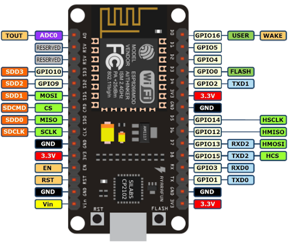
NodeMCU ESP-12E Devkit. Note input power pin Vin at bottom left. Note this PCB version does not bring VUSB to the pins


The answer is yes. And not really. Let me explain. You can power it from the input power pins Vin and GND. Or you can use USB port. Or both even of them at once. At a pinch you can even power it from the 3.3V pin. Powering it with 12V at Vin will work, but the AMS1117-3.3 LDO regulator will heat up badly under normal operation. It might even do a thermal shutdown and cause the ESP8266 to reset.

Powering from the micro USB port is easiest. You attach a smartphone charger cable to it; there is no wiring to do and you can even use it to program the Devkit. The USB port supplies 5V, and the power rail is usually called VUSB.

The NodeMCU Devkit is usually sold as a 5V device. A quick look at the board shows an AMS1117-3.3 Low Drop-Out linear regulator is connected to Vin. It produces the 3.3V needed by the ESP-12E module. But the AMS1117 datasheet specifies a maximum input voltage of 18V:

AMS1117-3.3 maximum input voltage is 18V

Now it is possible that other components on the Devkit PCB might require Vin to be 5V. A look at the schematic is advisable. I got mine from here. The schematic names the Vin voltage rail VDD5V. The USB rail is VUSB and the 3.3V rail is VDD3V3. Happily there are only 3 components that use Vin:

NodeMCU Devkit Vin Power schematic 

Note the schematic even specifies a Vin maximum of 20V. This is because it uses an ON Semiconductor NCP1117ST33 LDO which has a maximum of 20V. Notice C7 is rated at 25V. 

VDDUSB and VDD5V are linked via the schottky diode 1N5819. The 1N5819 is not a problem; it is a 40V 1A device. The problem is it comes in a tiny SOD323 package just 1mm by 2mm in size. This is not going to dissipate much heat. Its thermal resistance is 380 degrees Celsius per Watt. Its forward voltage drop is 0.6V and if it were to carry just 500mA current the temperature would rise 114 degrees. 

So if you have both Vin and VDDUSB connected, and you did not happen to have Vin turned on, depending on your power supply, VDDUSB might supply too much current to it and burn up. It is probably safer not to use VDDUSB if Vin is much higher than 5V.

SOD323

The AMS1117-3.3 comes in a SOT-89 package. This looks a lot heftier than SOD323. From richtek, the thermal resistance is 135 degrees per Watt. Now we are likely to get better performance because the IC is soldered onto PCB copper traces which will help it dissipate heat, but from Torex this is no better than 76.9 degrees per Watt.

Now my NodeMCU Devkit running its IoT program at 80MHz will take 80mA at 3.3V. This is supplied by the AMS1117-3.3. Now if Vin is 12V, the AMS1117-3.3 is a linear (not buck) regulator, and it will have to dissipate a whopping 8.7V at 80mA or 696mW. At 76.9 degrees/W the temperature rise is 53 degrees. My ambient temperature is often 34 degrees in balmy Malaysia, so that makes 87 degrees Celsius at best.

At worst it is 128 degrees Celsius, perilously close to thermal shutdown at 150 degrees Celsius. So that was why Vin was specified as 5V by the manufacturer.

Since the issue is just heat and not voltage level, instead of using a 5V buck converter to lower my Vin, I could simply put a reverse-biased 6.8V Zener diode in series. Say a hefty 1N4736 weighing in at 1W. This will take 544mW off the AMS1117-3.3 which now should clock in at a comfy 46 degrees (ie 11.7 degrees rise).

Now many of the super-cheap NodeMCU have, shall we say, quality standards that are somewhat permissive. In my case AMS1117 was used in place of NCP1117, lowering the maximum Vin to 18V. C7 might also be derated to 6.3V. Your mileage may vary.

Also it is advisable not to debug with the USB port and 12V connected. If you have to do it connect it to your computer using a powered USB hub. That way if things goes South, you do not lose a motherboard. And if like me you develop your gizmos DevOps fashion, it is also advisable to install ArduinoOTA so you can update the ESP8266 program via WiFi. 

This removes a future temptation to stick a USB debug cable into a 12V system. If you are unlucky and the 1N4736 fails short-circuited (after all, it runs hot) there will be 12V at Vin. A thermally shut down ESP-12E often looks very much like it has faulty software! 

For my 12V LED lamp I used a NodeMCU L293 motor shield with my Devkit so I mounted the 1N4736 zener directly to the 12V and Vin terminals (see photo above). It worked well for me. After 3 hours at 33 degrees Celsius ambient, the zener diode got pretty hot; too hot to touch, but the ASM1117 was only slightly warm.

Happy Trails.


Sunday 3 January 2021

Fiber optics for the Home Network


“We cannot live only for ourselves. A thousand fibres connect us with our fellow men; and among those fibres, as sympathetic threads, our actions run as causes, and they come back to us as effects. ” – Henry Melville

Fiber optics networking, is normally expensive and fragile. Telecoms-grade equipment come to mind. Maybe we even have a broadband fiber to the house (helpfully called FTTH). This usually ends in a telecoms-supplied box, Passive Optical Network (PON) into which we plug out usual copper (ie RJ45 UTP) LAN cable.


Fiber broadband usually ends in copper LAN connection


But why would I even want fiber for home LAN? Regular readers will know my house is on a hill which regularly gets struck by lightning. We get used to being off-grid for the duration of the storm, which happily is not usually long. But it would be nice not to have damaged electronics. Even better if we can cut over to UPS and keep watching IP TV or youtube. If my copper LAN cable runs are too long (maybe 30m) lightning often damages the network switches, or even fuse the UTP connectors together.

A Huawei ONT 'fiber modem' commonly supplied with Unifi fiber broadband


Or you might want more reliable and secure links for your security cameras/CCTVs which are often outdoors and at the end of long cable runs. Maybe you want to share your neighbor's broadband connection. 

Or maybe you simply want to speed up/secure that wireless WiFi repeater for when you are at one end of the garden. High speed WiFi is well and good, but once your neighbors have theirs installed the airways can get pretty crowded. 

Fiber LAN often means using telecoms equipment which are not only expensive but often not available to the general public. First, the fiber optic cable. Your best chance would be to use the type that your local telecoms monopoly/behemoth uses. High manufacturing volumes usually mean lower prices. Here in Malaysia it is  G.657 Class A single mode fiber.  A 1000m roll of outdoor cable costs less than RM200 (USD50) and even RM100 (USD25) if you are willing to order from mainland China. That is comparable to a 300m roll of copper Cat 5 UTP LAN cable. 

1km roll of G.657 Class A single mode fiber


But fiber cable is more fragile? Yes, if you used the equivalent indoor drop cable. The outdoor cable is often extremely strong. Mine consisted of not one but 3 steel cables reinforcing the fiber cable. I have had tree branches pulling it almost to the ground and the fiber core remained unbroken. They are often stronger than the copper UTP cables.

Outdoor fiber cables are often extremely strong

The outdoor fiber cable is far more heavy but they are still smaller than the Cat 5 or 6 copper cable. It is surprisingly bendable, considering fiber optics is a glass. And since there is no ohmic contact, you can run the cable parallel to the mains cables, in the same cable trays or conduits. This greatly reduces cabling costs.

Most indoor fiber is limp and frail


OK, but what about the fiber optic interface to the computer? A single mode single core fiber cable specifications are something like this:


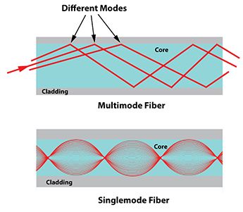
The last line reads 850/1300nm: it carries just 2 light frequencies. If you need more channels you need to run another cable. The traditional multi-mode cables carries lots of frequencies, but with a price tag to match.

Poor cousin: single-mode versus multi-mode fiber


We will be needing something to convert between UTP and fiber: two fiber modems, one at each end. As usual the Chinese have something cheap and cheerful (only RM25/USD5) called a media converter: the HTB-3100.

The HTB-3100A and HTB-3100B are sometimes sold as a matched  pair

Now this being a Chinese no-name box, be careful to look for a media converter that has only one fiber SC UPC port. The picture above shows two (marked TX and RX) but only the TX port can be uncovered. If you, like me, happen to buy the dual-port box by mistake you will need to lay 2 fiber cables for every copper UTP connection. You want to look for WDM (Wavelength Division Multiplexing). To carry 2 channels in one fiber, it transmits in one wavelength, 1550nm and receives at another, 1310nm. That is Type A. Type B is just the reverse, transmitting at 1310nm and receiving at 1550nm. You will be needing one unit of each type. They are often sold in matched pairs.

Both the single fiber and dual fiber media converters might be labelled as Half/Full Duplex. My guess is this refers to the UTP (ie RJ45 or copper) end. These days most CAT5 or CAT6 copper LAN cables come with both TX and RX pairs, and Half Duplex might be when Ethernet is negotiated down to CSMA/CD. 

Last but not least there is the complex matter of cutting, splicing and terminating your fiber optic cable. Years ago, it took expensive equipment, highly-trained operators and extremely clean conditions, which are sometimes difficult to do on-site. But for now there is and end-run, a workaround. Again from the Chinese. You can buy the cables already terminated for very low prices. Like RM36 for 50m. That is just USD9.

Pre-terminated outdoor single mode fiber cable.

Some suppliers will do it to a custom length. Just make sure the connector is SC UPC (it is easy to specify the incompatible SC APC or LC connectors). Now I had coax 10Base2 concealed LAN wiring installed in my house (yes, yes I am a dinosaur), so it was an easy matter to rip it out of the conduits and install the smaller fiber cable in it place.

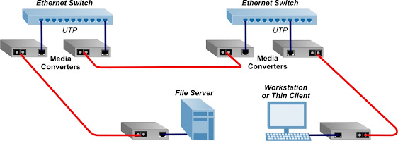
The aim is to replace your long copper cable runs with fiber. One benefit is if the cable run is over 100m you do not need to install the repeaters (ie LAN switches) that UTP Ethernet needs. If you add in the cost of the power wiring, enclosures, the savings quickly pile up.

The aim is to replace long copper LAN cable runs with fiber (in red)


It worked so well I ran another 100m fiber cable outdoors to my home office so I can share the broadband. The system has been in place through several violent thunderstorms and one fallen tree and did not miss a beat.

If you live in Malaysia, you are in luck, for Talikom Malaysia, the telecoms monopoly mostly uses sub-contractors to install your FTTH fiber cable. For a very reasonable fee, not exceeding the cost of a roll of fiber cable, they can be persuaded to do your internal house fiber cabling. In my case it was money well spent for much of the work involved climbing onto the roof. A huge advantage is they will splice and terminate your fiber cable using proper equipment, resulting in a very good connection.

The only thing left would be an inexpensive way to cut, join and terminate a fiber cable myself. But that is for another post.

Happy Trails.