 |
| NodeMCU Motor Shield with ESP-12E Devkit and 6.8V 1W Zener diode |
Sometimes it makes sense to use a single power rail, like when I was making an IoT dimmable LED lamp using the NodeMCU ESP-12E Devkit. The strip of LEDs required 12V and I was loath to use a 5V buck converter: it would just be another item to mount. So, can I run the NodeMCU Devkit on 12V?
 |
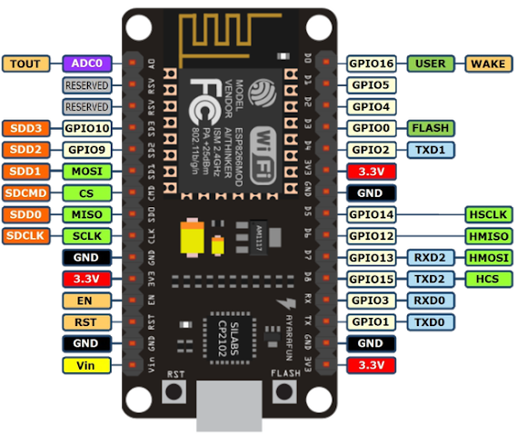
| NodeMCU ESP-12E Devkit. Note input power pin Vin at bottom left. Note this PCB version does not bring VUSB to the pins |
The answer is yes. And not really. Let me explain. You can power it from the input power pins Vin and GND. Or you can use USB port. Or both even of them at once. At a pinch you can even power it from the 3.3V pin. Powering it with 12V at Vin will work, but the AMS1117-3.3 LDO regulator will heat up badly under normal operation. It might even do a thermal shutdown and cause the ESP8266 to reset.
Powering from the micro USB port is easiest. You attach a smartphone charger cable to it; there is no wiring to do and you can even use it to program the Devkit. The USB port supplies 5V, and the power rail is usually called VUSB.
The NodeMCU Devkit is usually sold as a 5V device. A quick look at the board shows an AMS1117-3.3 Low Drop-Out linear regulator is connected to Vin. It produces the 3.3V needed by the ESP-12E module. But the AMS1117 datasheet specifies a maximum input voltage of 18V:
 |
| AMS1117-3.3 maximum input voltage is 18V |
Now it is possible that other components on the Devkit PCB might require Vin to be 5V. A look at the schematic is advisable. I got mine from here. The schematic names the Vin voltage rail VDD5V. The USB rail is VUSB and the 3.3V rail is VDD3V3. Happily there are only 3 components that use Vin:
 |
| NodeMCU Devkit Vin Power schematic |
Note the schematic even specifies a Vin maximum of 20V. This is because it uses an ON Semiconductor NCP1117ST33 LDO which has a maximum of 20V. Notice C7 is rated at 25V.
VDDUSB and VDD5V are linked via the schottky diode 1N5819. The 1N5819 is not a problem; it is a 40V 1A device. The problem is it comes in a tiny SOD323 package just 1mm by 2mm in size. This is not going to dissipate much heat. Its thermal resistance is 380 degrees Celsius per Watt. Its forward voltage drop is 0.6V and if it were to carry just 500mA current the temperature would rise 114 degrees.
So if you have both Vin and VDDUSB connected, and you did not happen to have Vin turned on, depending on your power supply, VDDUSB might supply too much current to it and burn up. It is probably safer not to use VDDUSB if Vin is much higher than 5V.
 |
| SOD323 |
The AMS1117-3.3 comes in a SOT-89 package. This looks a lot heftier than SOD323. From richtek, the thermal resistance is 135 degrees per Watt. Now we are likely to get better performance because the IC is soldered onto PCB copper traces which will help it dissipate heat, but from Torex this is no better than 76.9 degrees per Watt.
Now my NodeMCU Devkit running its IoT program at 80MHz will take 80mA at 3.3V. This is supplied by the AMS1117-3.3. Now if Vin is 12V, the AMS1117-3.3 is a linear (not buck) regulator, and it will have to dissipate a whopping 8.7V at 80mA or 696mW. At 76.9 degrees/W the temperature rise is 53 degrees. My ambient temperature is often 34 degrees in balmy Malaysia, so that makes 87 degrees Celsius at best.
At worst it is 128 degrees Celsius, perilously close to thermal shutdown at 150 degrees Celsius. So that was why Vin was specified as 5V by the manufacturer.
Since the issue is just heat and not voltage level, instead of using a 5V buck converter to lower my Vin, I could simply put a reverse-biased 6.8V Zener diode in series. Say a hefty 1N4736 weighing in at 1W. This will take 544mW off the AMS1117-3.3 which now should clock in at a comfy 46 degrees (ie 11.7 degrees rise).
Now many of the super-cheap NodeMCU have, shall we say, quality standards that are somewhat permissive. In my case AMS1117 was used in place of NCP1117, lowering the maximum Vin to 18V. C7 might also be derated to 6.3V. Your mileage may vary.
Also it is advisable not to debug with the USB port and 12V connected. If you have to do it connect it to your computer using a powered USB hub. That way if things goes South, you do not lose a motherboard. And if like me you develop your gizmos DevOps fashion, it is also advisable to install ArduinoOTA so you can update the ESP8266 program via WiFi.
This removes a future temptation to stick a USB debug cable into a 12V system. If you are unlucky and the 1N4736 fails short-circuited (after all, it runs hot) there will be 12V at Vin. A thermally shut down ESP-12E often looks very much like it has faulty software!
For my 12V LED lamp I used a NodeMCU L293 motor shield with my Devkit so I mounted the 1N4736 zener directly to the 12V and Vin terminals (see photo above). It worked well for me. After 3 hours at 33 degrees Celsius ambient, the zener diode got pretty hot; too hot to touch, but the ASM1117 was only slightly warm.
Happy Trails.
No comments:
Post a Comment