Showing posts with label Repair. Show all posts

Sunday, 30 May 2021

Repairing the PICkit 2


Microchip PICkit 2 Programmer

My PICkit 2 failed:

$./pk2cmd -PPIC16F1705 -GC
Read successfully.
Configuration Memory
0000 0000
VPP Error detected. Check target for proper connectivity.

PICkit 2s are not expensive, more so the China clones now available online. Neither is its successor the PICkit 3, so I could easily have thrown it away. But it came with a great manual, complete with source code and  schematics which is uncommon. Plus the original PICkit 2 is getting hard to find these days and PICkit 3 might have issues supporting some legacy CPUs. In any case I could repurpose it: not only it is a USB device, it has a ready-made connector with 2 IO ports and a nifty 12V-0V pin. 

A VPP error is probably to do with the MCLR pin:

Pickit2 JTAG Connector              Function
        Pin 1                                     MCLR/Vpp 
        Pin 2                                     Vdd 
        Pin 3                                     Gnd
        Pin 4                                     Data 
        Pin 5                                     Clk
        Pin 6                                     N/C

6-way header


To check MCLR(pin 1) I just stuck a 6-pin header into the PICkit 2 connector and measured it with respect to Pin 3 (Gnd). It helps to make a little bash script:

$cat ./testpickit2
for i in {1..5..1} 
do 
  sleep 5
  ./pk2cmd -PPIC16F1705 -GC
done

MCLR (or Vpp) schematic diagram 


The multimeter measures MCLR at 0.15V. A sanity check with a good PICkit 2 showed this goes well up to 12V. The schematic shows an ingenious DC boost converter, using the CPU pin Vpp_Pump to periodically short the inductor L1 to ground. There is even Vpp_FEEDBACK pin to regulate its output. Two additional CPU pins, Vpp_ON and MCLR_TGT are used to switch the resulting regulated high voltage to pin 1 of the JTAG connector (ie the programming port).

I pried open the plastic case and the repair job just became a lot simpler. L1 the 680uH surface-mounted inductor fell off the PCB!


Detached inductor L1. The original position is circled in red

This happens quite a bit with surface-mounted components, particularly when subjected to mechanical stress. The inductor is among the tallest component and would have been compressed by my fingers through the thin plastic case.

680uH Inductor. Note the plastic former is plated at the ends and the inductor wire is then soldered on.

The plastic, metal-plated lead has snapped off one end. I thought it would be a slam-dunk to solder the unbroken end back on the PCB and solder the broken wire directly to the PCB. Boy I was wrong: the wire was so thin it was hardly visible under high magnification. Worse, when I stripped the enamel insulation using my soldering iron, this made the wire brittle and it eventually broke off.  

New inductor (bottom left) is larger than the original


A new 680uH inductor, 74404054681 INDUCTOR, 680UH, 0.25A, 20%, SEMI-SHLD from element14 cost RM5 (USD1). I chose it to match the leads pitch of 4mm; the other dimensions were uncomfortably larger than the original but this was the only part with a reasonably sane delivery date. I was concerned it might be too tall and prevent the plastic case from snapping shut.
Working PICkit 2


Soldering was a little tight: you need to solder the right-hand lead first and slide it right to make room for the iron tip at the left lead. But there was a happy ending: the case snapped shut and the PICKit 2 worked.
     

Wednesday, 12 May 2021

Development System for the ancient Microchip PIC16F57 CPU


Microchip PICkit 2 Programmer with target system

The Microchip PIC16F57 is an ancient CPU, long superceded and only grudgingly sold by Microchip Inc. Indeed there is currently a 2-month wait for them. It has a tiny 2K word program memory and a microscopic 72 bytes RAM. Too small to use with C, To program it, you would need assembly language. Why would I want to waste time on something like that? 

I have a remote gate opener ('autogate') which I tinker with unmercifully. It is also underneath an powerhead mains power pole which seems to get struck by lightning a few times a year, so over the years I accumulated a stack of dead S-1 controller boards which I usually repair and reuse. Except for those few which had dead CPUs.

S-1 Autogate Controller Board

Now they are cheap enough: RM100 (USD25) will buy you one online. But repairing these last boards meant replacing the CPU, which meant writing the program for it. After some effort, I noticed that the CPU footprint is an exact match for the Microchip PIC16F57, and I even have one in my CPU tray.

Writing the program also means I can upgrade the CPU to a newer one, and maybe add WiFi connectivity as well. And since the Chinese can sell me the board cheaper than I can make it, it does not make sense to make my own PCB. To upgrade it I would first have to replicate its functions, and that means writing the program from scratch.

But before I can even do that I have to find an Assembler, device programmer and build a little target system (PIC16F57 CPU board) just to make sure the toolchain works.

Microchip's MPLAB Version 8.33 (an equally ancient version running on Microsoft Windows XP) works for me. It comes with the MPASM assembler which happened to support the PIC16F57. You can try your luck with the latest and greatest MPLAB, but if it does not work out, you can get Version 8.33 from the Microchip MPLAB archive. I run a Windows XP image from a Qemu-KVM virtual machine and use pk2cmd with my PICkit 2 programmer, but you will probably be quicker off the mark with a Windows XP laptop.

The next thing you need is a little PIC16F57 (ie target) board just to accept the PICkit 2 connector and also run a small test program.  

PIC16F57 target system


Then you need the test program which you feed into your MPLAB assembler and produce the hex file the PICkit 2 needs to program the CPU. Usually you can find such sample programs in the great wide Internet but for some reason, not for the PIC16F57. You can find the schematics, hex file and source code here in my github repository.

To program the PIC16F57 I use:

$./pk2cmd -PPIC16F57 -Fledblink.hex -M

To run it I use:

$./pk2cmd -PPIC16F57 -GC -T -R

Some notes of caution: my experience is a Microchip CPU in a new target system can be hard to start. The combination of your choice of oscillator affects the Power-on Reset Timer delay. The MCLR reset circuit also changes things. You also need to sort out you Reset and Watchdog Timer vectors without which you program will not start. Once you get past that it is usually plain sailing. Using a Microchip Development Kit makes real sense here, but they have long since abandoned the PIC16F57. Also having a known good toy program helps when you are trying to start the CPU.

Despite having only 2K the PIC16F57's memory is also segmented. The simplest way is to ensure the program sits within page zero 000-1FF. This is because subroutines calls only work within page 0. You can next just 2 levels of subroutines.

Lastly the digital output pins are set and cleared (ie BSF and BCF) using a Read-Modify-Write mechanism. This means the CPU does not keep a record (ie a register) of your IO bits. It also accesses IO 8 bits at a time and if it executes a write, it will first read the whole byte from the external circuits, modify the read data and writes back the 8 bits. This can have unexpected effects if you are not running within the electrical operating limits (ie driving too much current into an LED). Also a CPU IO write followed immediately by a read may execute too fast for the external circuit.

The RC system clock circuit is a little hard to time accurately because of its inherent inaccuracy and component tolerances. If your LED does not blink, you might need to adjust the delay intervals. If that fails, seek to dim the LED rather than blink it.

This is a hard-core RISC instruction set, running in a Harvard Architecture (ie program and data busses are separate). There is usually no substitute to reading every single word in the datasheet.

If this is your first time with assembly language, congratulations. You have talked to a CPU in its own language, mano a silicona, and it understood you. 

Good Luck, and Happy Trails.   

Wednesday, 5 May 2021

SMD Hot-Air Rework Station Repair


Ya Xun Hot-Air Rework Station cost just RM209 (less than USD50) 

Last year I bought a cheap hot air rework station. It was probably not a good idea - I have never used one before, and this being pandemic season, I would be on my own. My eyesight is not getting any sharper but the electronic components are definitely getting smaller. On the other hand, all the fun stuff nowadays, like ESP8266, Aduino and Raspberry Pi all seem to use Surface Mount Devices. And most compellingly, SMD parts are much cheaper than their through-hole equivalents. 

Some SMD components are just about manageable using old-school soldering irons


I found myself buying soldering irons with smaller and smaller tips, right down to 0.5mm. With discrete SMD I simply used two irons (I would have used more but I ran out of hands): you can often heat up the entire thing and lift it clean off with two irons. To solder a new SMD part in I used the 0.5mm iron. SMD ICs were a problem: sometimes you just could not heat up all the leads with two irons. But if I had new ICs on hand I would simply cut the IC off the printed circuit board. You then removed each soldered lead one by one. 

You need a small and really sharp pair of micro-cutters. Anything less and the leads tend to get ripped off along with the tiny PCB pads. That cutter you never lend out or use for anything else. You guarded it jealously and threatened anyone with immediate bodily harm if he tried to take it.

Duratool's micro cutter: don't leave home without it. 


But QFN and BGA SMD packages were quite another thing. The contacts and PCB pads are underneath the body, and only a hot air gun will get them off without damaging the PCB. Well, I could sneak the PCB into the wife's oven in the kitchen, but this tends to remove all the parts. To inspect the soldering, one would need nothing less than an X-ray machine. 


QFN (Quad Flat No-lead) IC

BGA (Ball Grid Array) IC

Even when there are no BGA or QFN parts, sometimes there is simply not enough room to place the irons, and neighboring parts may get moved, burnt or worse. But then came a China siren to lead me into temptation: at only RM209 (less than USD50) the Ya Xun 850A+ cost about as much as a Raspberry Pi 4. The clunky box may even be an advantage - it is less likely to use SMD parts, which makes it repairable with soldering irons.

China temptress

In about a year it failed completely: it blew its fuse. After replacement, its temperature LED no longer lit up and the hot air flow is no longer adjustable. I whipped off the cover and got the PCB out. Usually I could figure put most PCBs but looking at the parts mounted. But only if I am already familiar with them. There is just one problem: I had never worked with triacs before and this board had two, in essentially AC power "dimmer" type circuits. This means to make any sense of it I would need to first trace out the schematic. Oops.

YX850A+ Controller PCB: old-school single-sided PCB with through-hole parts

Warning: this repair deals with lethal voltages. Do not attempt unless you have been properly trained!

The PCB used old-fashioned through-hole components as expected. Even better,  the PCB is single-sided: it only has traces on the bottom (ie solder) side. This makes it easy to trace the leads; PCB traces o the component (ie top) side will run under the parts and be obscured. Single-sided PCBs are also easy to desolder. 

Tracing the PCB was not so bad, but having worked with a human PCB designer for over 10 years, hand-drawing schematics felt lame so it seemed like a good idea to install geda again. Two weeks later, armed with the schematics and a wobbly knowledge of triacs and diacs, the repair work began.

The first problem was the internal wiring was badly crimped; the wires were the wrong sizes and the resulting crimped joints were loose, in particular those at the front panel switch.

Loose crimp connectors at the panel switch (top) and temperature sensor wiring (bottom)

The front panel main switch switches in both mains AC and 12V DC to the PCB and loose joints here cannot be healthy for the triacs. And sure enough the triac Q2 BT136-600 is shorted Gate to T2. The LED D1 which indicates airflow was also shorted, together with its series rectifier D2 (1N4007). Unusually, the LED appeared to be driven directly by the triac output AC and is probably more sensitive to line surges. The PCB trace from D2 to Neutral was melted a good 4mm. 

BT136 triac and associated components

The gate drive diac, D4 (DB3) and its series capacitor C5 (120nF polyfilm) were also shorted. Now triacs are turned on using the gate, but can only be turned off by letting its load current drop to zero, which means interrupting its input mains. This is done using a relay K1 (HK4100F-DC12V-SHG an Omron G5V-1 equivalent). The relay is powered from 12V output from U3, an LM7812 linear regulator which was also shorted input to output.

The other triac, a BTA12-600 supplying the heater seems to be fine. The heater LED failure was due to a loose temperature sensor wire. The heater is probably a lot less inductive than the air pump motor. It also helps it is triggered from another optically-isolated triac U2, an MOC3023. Interestingly the MOC3023 drives the main triac's gate using a series rectifier D4 (1N4007) which means it only puts out half the AC waveform and pretty much guarantees the BTA12 turns off during the other half cycle. The MOC3023 is in turn driven by the temperature sensor via U1, an HA17358 (probably an LM338 workalike) which seems none the worse for wear despite being exposed to unregulated 25Vdc from the shorting LM7812. The 40V maximum of the LM338 probably helps.

Repair was easy. The parts easily dismounted and replaced. The dodgy crimp connectors were soldered to their wires. Replacement parts were cheap and arrived quickly despite the pandemic-induced parts shortage. The Malaysian branch of Element14 in particular offered free delivery, in contrast Digikey wanted USD89 to deliver a USD2 part.

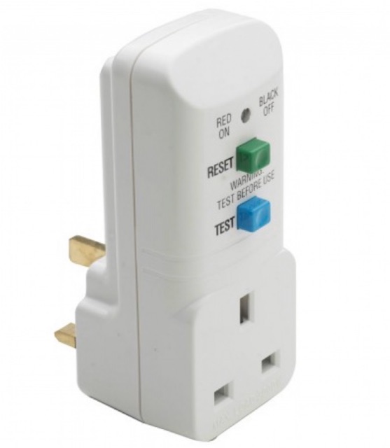
To test, I used a 300VA isolation transformer dialed down to 220Vac (China boards are rated for 220V; Malaysian grid is 230V but I am at the very end of the mains power line at a feisty 240V). For additional safety I also used a portable ELCB (RCD to Americans). Since some semiconductors (usually mains bridge rectifiers) are connected directly to mains AC sometimes there is a short from  Live to DC ground, and an ELCB will pick this up.

Portable ELCB

An isolation transformer is a two-coil transformer (ie not an autotransformer) putting out the same voltage level as its input. If the output is shorted, the current is limited by the magnetic flux saturating in its core, limiting power delivered to its VA rating. 

110Vac Isolation Transformer. Note the Earth line passes through but Live and Neutral are isolated. 


It often lets you diagnose faulty boards before it completely burns out. 60VA, or even 30VA are very handy ratings, and the idea is to progressively work up to the full device rating. I always make my own; a handy way is to use two regular (ie step-down) transformers connected back to back. To dial down the output voltage you will need to use a variable transformer to drive the isolation transformer.

2000VA Isolation transformer from Carroll & Meynell


Testing was straightforward except for one thing: the air pump continued to run despite the panel power switch being turned off. Despite having used it for a whole year, I did not really notice if it did that before. My excuse was I was struggling with tiny SMD parts. Having the air pump run meant the BT136 is on. Was the relay turning off?

Air pump relay circuit

I needed to make some live measurements. This is never a good idea when dealing with stuff connected to mains AC. The isolation transformer protects the repair item but will easily deliver a fatal shock to a human (50mA or 15VA will ruin your day, probably your life) . The mounting wires are short and the board has to be mounted vertically which means reaching past exposed live bits to probe.  

Thus far I had looked for defective parts the safe and preferred way: offline, unpowered and using a digital multimeter. If you suspected something you took it out and make some more measurements. When testing I powered up at low VA, operated the panel knobs and switches and avoided touching exposed parts. 

NPN transistor Q6 (SS8050) was an immediate suspect - with the panel switch off, its collector was 6V, way lower than the 12V if it were off. Maybe it was leaking? It tested OK dismounted: both semiconductor diode junctions seemed OK, but maybe it was partially leaking? I replaced it with a generic 2N2222 (watch it: ON Semi produces a PN2222 with reversed leads unlike my KSP2222A), but there was no change; the air pump kept running even though the panel switch is off.

An examination of the circuit provided a clue. In addition to switching in mains voltage, it also switched on 12V to Q6 (and the opamp). The capacitor C6 is 220uF and will store a walloping charge and R19_2 measures about 100K in-situ but is probably higher (the color codes are faded with heat). When switched off, it will ensured it discharged slowly into the base of Q6. The time constant is in the order of 22 seconds. And always fearing a defect I had been quick to cut off power to  the isolation transformer while testing.

Using this formula, my Change is 95% (12V to 0.6V) at time constant 22 will result in a delay time of 64.8s. I assembled and tested it again; and sure enough after a long minute the air pump went off. But why would it want do that? It is somewhat misleading to have the power on even after the panel switch is off.  The manual for a similar system yielded this clue:


Ah, that was unexpected, but at least it was not broken. I would recommend you spend that minute, set the airflow to maximum and wait for the air pump to finish doing its thing, and then turn the YX850A+ off at the power socket, for the manual goes on to say:


An auto-disconnect would be nice, maybe a few seconds after the air pump turns off. So would a thermal cutoff switch. And the triac heatsinks looked puny with the cooling fins horizontal instead of vertically where they would do most good. But that is a project for another day. 

There you have it: Hot-Air SMD Rework Station Repair.

Happy Trails.


Thursday, 5 November 2020

Once more unto the breach, dear friend, once more ... APC Back-UPS RS1000 Repair


APC Back-UPS RS1000

I first encountered it 13 years ago, in 2008. Even then it was past its prime, bought at a private auction for peanuts. It started up, then indicated 'overload' and shut down. Back then I needed to learn about UPS and the RS1000 was a nice roomy design and a large PCB which seemed easy to work with.

Main PCB: top of picture is front of UPS. Charging section is on the bottom left corner


You took out the screws and lifted the front cover from the middle in 2 sections. The bottom half covered the battery compartment. The top front flap had to be pried off together with the right side cover, and comes off with a nasty crack. Once exposed it was easy to reconnect the sections for testing.

Important: Do Not Attempt this Repair unless you are qualified. Not only there are hazardous voltages inside, it will continue to be hazardous if the UPS is disconnected from the mains. In additional since there are switch-mode power modules inside, connecting an oscilloscope to it will result in damage, fire or death.

It sat in my study for 2 months before I found the fault: there were two shorted MOSFETS, Q1 and Q2, IRF740. Replaced that plus a blown fuse and it worked again. I had a good guess at the root cause: there were signs a gecko used to live there. The nice roomy UPS must have been a good place for a gecko to keep warm.

Typical Malaysian house gecko 


It was some 9 years, in 2015 before it was brought in for repair again.  It started up, indicated 'overload' and shut down. Call me simple, but I went straight to the battery charging circuit. This time a deceased and mummified gecko was still in there. 


Bad Neighborhood: An IoT Power Extension used for lamps has a lot going for a gecko: lots of insects attracted to the light. It is warm, dry and safe from kingfishers, rats and other predators.  There is just one problem ... electrocution


Again two shorted IRF740s, this time Q1 and Q3. The PCB was getting a little beat up with the second rework, but it started up nicely.

It was a little quick to switch over to battery operation, but you could decrease the sensitivity by turning it off, then holding the button down until all 3 lights lit up. Then you pressed the button again to select: one light for minimum sensitivity. 

And back it goes into service. It came back 5 years later, about 4 months ago this year. This time there was nothing wrong, and everything wrong: the owner did not need it anymore. Desktop computers are now notebooks with 3 hour or more battery life and there is little use for a UPS with a backup time of 15 minutes.

For four months it backed up my npm server, a laptop. During one long power outtage, it got quite hot and right after that would not go back to 'online' mode even after the power came back. There is AC power in its non-battery-backed power sockets, and it charged the batteries when it is shut down. But when it is started up, it tests the batteries, then the mains voltage, and switches to battery operation. 

Perhaps after a few years its 'Line Sense' circuit had deteriorated. Maybe a gecko had set up shop in it again. My first thought was to throw it out: there was little use for it. But then a half-hearted google search turned up the full schematics for it!

Well maybe one last hurrah. If I moved my npm server to a raspberry pi 3, it should be able to run on battery for 2 hours or more.


So off with the cover. This time there was no gecko. Just the 'Line Sense' problem. The components are surface-mount but just about large enough to handle without an airgun.

The first opamp in IC8 (LM358) is a difference amplifier. It reads the incoming mains AC directly, using 2M series resistors to step down 325V (230Vac nominal is 325 Vpeak) to around 3V.


Line Sense (IC8). CPU is at top center.


The second opamp is (I think) a precision half-wave rectifier which is read directly by the CPU analog input. The 'Sync Circuit' output is connected to the CPU digital input, probably used to sense zero crossings for a smooth switchover.

When I measured the resistance of the resistors, diodes and opamps (with power off and circuit discharged!) they seems OK, nothing short or open-circuited. Next would be a power test. Plugging in the battery alone did not produce power at the LM358.

But plugging in the AC mains (with the UPS still shut down) did. 12V supply came up. But the negative rail '-8V' seemed a little low at -4.2V. Now the AC mains Live is connected to the opamp inverting input, and it can only go as negative as its voltage rail. The precision rectifier will rectify it to the correct polarity for the CPU analog input. If the negative rail is not low enough, the Live voltage sensed will correspondingly drop. This seems to square with the observed fault.

So we go on to the -8V power schematic.


Maybe the designer is old-school, but this is a flying-capacitor charge pump, straight out of the textbooks. Most of the kids would have dropped in a cheap surface-mount DC-DC IC. The CPU digital output line 'pumps'  CHRG_PUMP_OSC at a fixed frequency. This provides 12V on an off to the 'flying' capacitor C40 which charges up to 12V via Q25.

C20 is prevented from discharging by the diodes D21. Their polarities ensure that the output is negative, which allowing for diode forward drops and Q25's Vce, -8V seems a reasonable final output.

But what could be wrong?  There is some output, just a little low at -4.2V. Q25 or Q26 could be defective. It could be D19 shorting or D21 leaking. But the most likely is C41 and C40 has lost most of their charge. Electrolytic capacitors contain electrolyte, and is likely to dry out. They have a shelf life of 6 months before they are out of spec. And it has been, what, 12 years?

Again, with power off and battery disconnected and the PCB allowed to discharge, diode-tested the diodes and transistors (a bipolar transistor is simply 2 diodes stacked up). They seemed OK. This leaves the capacitors.

220uF test capacitor soldered across C41. 
 

To test the capacitors C40 and C41 it seemed easiest to simply parallel a new capacitor across the old one. In fact just adding one capacitor should improve the resulting output power. If possible, over-size the rating (I used 220uF) a little as the old one will act more as a load. I simply soldered it across C41.

On connecting the battery and mains voltage the voltage went up to -5.8V. And even better, when the UPS was started up, it tested the battery, then switched to 'online' mode!

For final repair, I ordered some surface-mount 22uF capacitors. There is nothing wrong with my 'test' capacitor, but the capacitor is heavy and lies horizontally when the RS1000 is upright and as a result may work itself loose after a few years.

[2020-11-10 update]: With new (Panasonic EEEHD1C220AR) SMD 16V 22uF electrolytic capacitors for C40 and C41, the negative rail "-8V" now measures -9.2V. Element14 is not the cheapest, but they hold local stock and I really did not want to wait 4 weeks with the UPS innards scattered over the work table.

So, it is "once more into the breach, dear friend". It's better to soldier on. Better the line of fire than the storage shelf.

Happy Trails. 

"How dull it is to pause, to make an end, To rust unburnish'd, not to shine in use!" - Tennyson, 'Ulysses'