Showing posts with label NodeMCU. Show all posts

Thursday, 19 January 2023

Electronics Without Semiconductors: The Strange Case of the VW Beetle (Bug) Fuel Gauge Regulator


Volkswagen Beetle (Bug) Type 1. Photo by Vwexport1300 

The fuel gauge in my 1969 VW Beetle (Bug) Type 1 failed. The needle kept indicating 'Full' no matter how much petrol I have in the tank. And the workshop said that a new meter assembly will need weeks to arrive and I really did not fancy driving with a jerrycan of fuel in case I ran out.

Now I know very little about cars; my thing is electronics and software. However, from 1968, the Beetle fuel gauge system is electrical (aha!), and armed with Speedy Jim's excellent webpage on Beetle/Bug fuel gauges, I got to work.

VW Beetle Type 1 fuel gauge schematic by Speedy Jim

The schematic shows a voltage regulator (quaintly called a 'vibrator') powering the meter in series with a potentiometer controlled by a float. The potentiometer and float ('sender') lived inside the fuel tank

VW  Beetle electrical type fuel sender 

The fuel tank is easily accessible for testing - just pop the front bonnet.

Beetle/Bug fuel tank. Sender is in front middle of the fuel tank

The output of the potentiometer (sorry - sender) connects directly to the gauge and is easily disconnected.

Fuel Gauge Sender Connector 

The fuel gauge is built into the speedometer, at the top middle. This explains the high replacement cost.


VW Beetle Speedometer: fuel gauge is top middle 

The cabling is at  the back, and luckily the wires are also easily accessible. 

Speedometer, back view. The regulator is riding on the meter's shoulder, on the left

Top view of mounted regulator. Photo by wagohn


Speedy Jim has a cut-out view of the fuel gauge; the current heats up a bimetallic strip and directly drives the needle. Far out! No magnet, no electrical coil. This is so cool. 

Picture by Speedy Jim

The regulator when dismounted looks like this, and is a little reminiscent of a 3-terminal regulator:

VW  Beetle/Bug Fuel Gauge Regulator

3-terminal regulator: LM7812 in TO-220 package

It is time to test. A quick check with the multimeter showed that my sender terminal is reading 5V with the ignition on. With the sensor disconnected the wire from the gauge reads 10.8V. With the ignition off the sender reads 18 Ohms. Speedy Jim has it as 73 Ohms empty and 10 Ohms full. After a couple of days running the sender read 28 Ohms. So the sender seems to be working. This is further confirmed by parking the Beetle uphill and then downhill to move the needle some more. 

Next is the test for the fuel gauge.  Speedy Jim (thanks, Jim!) has detailed instructions. With the wire disconnected (do not let it short to the VW body!), the gauge read empty. Short the wire to the car body and now it reads 'Full' as before.

This leaves the voltage regulator as the prime suspect. My guess was it shorted out its input to its output, and is applying the full 12V input voltage to the gauge bimetallic strip. Hence the constant 'Full' reading. Happens often enough in 3-terminal regulators. 
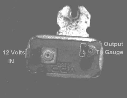
Regulator pinout: photo by Speedy Jim


Now rather than fumble around with my gauge, Speedy Jim has very handy pictures of a disassembled regulator.

Photo by Speedy Jim

There are no semiconductors in the regulator! It is not even solid-state: it is all metallic. The redoubtable Speedy Jim is worth quoting in full:

"... 12V from the battery heats up the heater element and warms the strip.  The thermal mass is small and the strip responds very rapidly.  As soon as it begins to move, the strip causes the contact points to open.  This breaks the circuit and the current ceases.  Now, the strip begins to cool off and bends back to its original shape, closing the contact.  This repeats, over and over.  The result is a series of pulses, each with a voltage of 12V.  When the pulses are fed to the gauge, the heater element in the gauge averages the pulses out.

The closer the pulses are together or of longer duration, the hotter the heater in the gauge will get.  By accurately controlling the pulses, the stabilizer has the effect of regulating the voltage (here, we're talking about RMS or "effective" voltage).  Suppose that battery voltage goes up (as when the generator increases output).  The heater in the stabilizer will heat up more rapidly and open the contact points sooner.  The result will be shorter pulses of 12V sent to the gauge.  The opposite happens when the battery voltage goes lower."

Diagram by Speedy Jim

The diagram leaves no doubt. Far from a humble LM7812, this is a switched-mode power supply. The diagram show a pulse-width modulated (PWM) output at a frequency of 3Hz and duty cycle of 33%. And all this using just metal. It is as if I decapped a SMPS controller IC like the MC34060 and all I found was solder and wire! Compare this to a typical SMPS:

Solid-state SMPS

And you cannot argue with the reliability: I got the Beetle in 1992 and that regulator must have lasted 30 years of steady use, in a harsh environment with lots of vibration and shock. I would have been pleased if a solid-state regulator lasted half as long. Since it is a 1969 model there is a good chance it might have lasted over 50 years.

Now since the switching rate is only 3Hz, it should be visible if connected to a light. Speedy Jim used a light bulb, but these days there are very cheap 12V LED modules, especially if you cut one off a strip light.

12V LED module: just connect directly to the regulator

I unhooked the sender wire and connected it to the LED module. It lit up but did not blink, so there is no switching by the bimetallic strip in the regulator. I ordered a cheap China part for RM28 (USD4) . This would just be a rudimentary solid-state regulator with just a zener diode and a limiting resistor. 

Now I do not recommend connecting anything electrical to the fuel tank much less 12V from a car battery that can potentially deliver 200A, so extreme care is necessary, in particular when you connect up the wires. Note that the current from the regulator is from the 12V car battery and is being limited by the coil in the fuel gauge so we will use that as the power source. Still the following section delivers a 12V PVM signal into the fuel tank potentiometer (as well as the fuel gauge) and there is always a risk of sparks, especially if you move the fuel tank.

But it was still a good 10 days before it arrived, and in the meantime it would be nice to actually produce those PWM pulses if only to see history in action once more ...

L293D Motor Shield for NodeMCU ESP-12E V2
 

I had been working on a WiFi-controlled L293D Motor Shield for ESP-12E NodeMCU and it produces 12V PWM pulses suitable for driving DC motors as well as LED lighting. It runs an Arduino sketch, and you can get a copy from github

The key change is to the PWM frequency:

analogWriteFreq(3); /* Arduino v1.8.5 only */

Note the current Arduino reference says that the minimum value is now 100Hz. However I am on an old version, 1.8.5 and I could dial down the PWM frequency right down to 3Hz, so your mileage may vary.

I disconnected the regulator from the sender, and wired up the motor shield thus:

Pinout for VW Fuel Gauge Regulator PWM

The LED module is used to observe the PWM blink rate. You enter your WiFi access point SSID and password, recompile and download the program into the ESP-12E V2, usually via the microUSB port.

You will want to test youe setup driving 12V LEDs instead of the sender. Since you want to connect to the fuel tank at the last possible moment. I set up everything, including the phone browser before I did so. In particular you do not want to accidentally reverse the polarity to the sender, either by miswiring or by using the program's motor reverse command. An LED indicator is better than a filament bulb here.

 Once the  program starts your 12V led module will start blinking at 3Hz. To send a signal to the fuel gauge, you use a browser (I used Google Chrome on my Android smartphone) and type in:

http://12.34.56.78:8080/pwm1/33

And the fuel gauge immediately started registering the petrol level in the tank. This is because the L293D produces a 3Hz pulsetrain at 33% duty cycle, just like Speedy Jim said.

And you can produce a zero fuel reading by:

http://12.34.56.78:8080/pwm1/0

A full tank reading is

http://12.34.56.78:8080/pwm1/100

And not wanting to push my luck, I took down the setup as soon as I could. 10 days after, the new regulator arrived and the VW fuel gauge was fixed. I kept the faulty regulator: it is a reminder that SMPS is a lot older than solid-state electronics.

Root cause: the heater element appears to have disintegrated so the regulator is stuck in the 'On' position and failing to switch off


Happy Trails.


Thursday, 23 December 2021

Remote Control of Hitachi RAC-EJ10CKM Air Conditioner


NodeMCU ESP-12E with Baseboard and IR transmitter. The clothes peg is used to hold the IR LED in place aimed at the air conditioner

I have often worried about leaving the air conditioner on when I am out of the house, so being able to remotely monitor and control it seemed like a good idea. Using its infra-red remote link seemed like the natural way. 

The go-to method would be to buy a spare remote and wire an ESP8266-based WiFi relay to the On/Off button, but just for kicks I thought it might be fun to hack the 38kHz remote datalink itself. That is the subject of another post, but having hacked it, I now need to transmit the On/Off code to the  air conditioner's indoor unit. 

As usual someone, in this case TaxeIT has beaten me to it. The relevant circuit here is the IR transmitter using an ESP8266 output pin to drive an IR LED via a 2N2222 transistor. I ripped an IR LED off an old DVD Player remote, and my power adapter is 9V DC from a long-dead ADSL modem. For ease of installation, the aim was to be able to park the transmitter as far away as possible and still reliably switch the air conditioner. I managed 2 metres; the Hitachi remote easily did 4 metres. My circuit is:

38kHz IR Transmitter Circuit

The is a good writeup on driving IR LEDs by 'E' here. I was probably a little conservative with my unknown LED for 'E' drives his IR204 at 200mA. The IR204 has a maximum continous current rating of 100mA but a peak current of 1000mA. Since the LED is only transmitting for milliseconds, this is probably OK. 

Bear in mind my circuit is for convenience only; I happened to have a nodeMCU baseboard V1 for my ESP-12E which lets you use up to 12V at the input. There is nothing wrong about using 5V and dispensing with the baseboard like TaxeIT. One of the advantages of 9V or higher is I have more headroom to drive more than one IR LED in series. Angling each LED in slightly different directions will greatly ease the problem of lining up the transmitter with the air conditioner receiver. Try not to overdo it: if there is more than one air conditioner, you might then accidentally switch the wrong one. 

The other reason to use a baseboard is it is easily powered by a battery or power bank, which makes it a lot more convenient to check out the possible installation points.

The decoded remote data is something like

const unsigned int HitachiAC_On[] PROGMEM = {3378, 1696, 448, 1255, 448, 398, 471, 398, 470, 398, 470, 399, 471, 397, 471, 399, 471, 406, 470, 398, 470, 398, 470, 398, 471, 397, 472, 1255, 449, 398, 471, 398, 471, 404, 471, 398, 470, 397, ....

Note that despite the Hitachi using the same button for On/Off, it sends a different bitstream on Off:

const unsigned int HitachiAC_Off[] PROGMEM = { 189, 63402, 2071, 133, 141, 79167
0, 3447, 1621, 512, 1189, 512, 355, 512, 355, 513, 354, 512, 355, 512, 355, 513,
 356, 512, 362, 513, 354, 513, 354, 513, ...

Which are simply timer intervals to alternately turn the LED on and off. The hack was a little difficult as the bitstream turned out to be unexpectedly long. This is apparently true of some of the Hitachi models. The ESP8266 Arduino code is based on IRremote, with a pretty good explanation here. The source code is in github.

To turn the air conditioner on, I use either http or MQTT. For http I use curl:
$curl --connect-timeout 2 -k http://12.34.56.78:8080/on
<!DOCTYPE HTML>
<html>
Aircond is on</html>

To use it with the MQTT server:
$mosquitto_pub  -t 'aircond/commands' -m 'StudyAC_On'

The MQTT server is typically started on power-up with something like:
$mosquitto -c /etc/mosquitto/mosquitto.conf

This works well as long as the transmitter is not more than 2m away and pointed directly at the Hitachi air conditioner, ie at the IR receiver in the bottom right corner. However, the command might be ignored if say the air conditioner is already on and the 'On' command is transmitted. This happens if for example someone else operated it via its regular IR remote. Worse if the WiFi command is used sometimes curl times out without completing the command. This happens especially when there are WiFi connection problems.

To resolve lingering doubts about failing to turn off the unit, I use a separate IoT system, a Raspberry Pi to visually detect the orange 'On' LED on the indoor unit. Now that seems like overkill, but that Pi can be to detect other events remotely like smoke detectors, thunderclaps, door bells, distress calls, etc. At some point. With a lot of programming. But you get the idea ... I integrated it into my Google Assistant smarthome server for the remote operation part. 

Here is a video of it in operation:

Youtube video of voice activation


There you have it, a remote controlled Hitachi air conditioner, an IoT air conditioner.

Happy Trails.

Sunday, 23 May 2021

I love cheap thrills: WiFi OTA for Microchip PICs


Cheap Thrills - Sia


"Come on, come on, turn the radio on
It's Friday night, and it won't be long
Gotta do my hair, put my make-up on
It's Friday night, and it won't be long
'Til I hit the dance floor, hit the dance floor
I got all I need
No, I ain't got cash, I ain't got cash
But I got you, baby
Baby, I don't need dollar bills to have fun tonight
(I love cheap thrills)" - 
Sia, Cheap Thrills

Firmware Over The Air programming (OTA) is all the rage with Internet of Things (IoT) devices. Ongoing privacy and security issues make it almost mandatory that they be upgradeable after installation. That usually means OTA upgrades using a smartphone App or a desktop browser.

For a hobbyist, or just plain fast and cheap development, few systems beat the ESP8266-based IoT OTA, ArduinoOTA. The ESP8266 has a few flaws. It is difficult to operate on small batteries: sleep mode still requires milliamps and while using WiFi it can surge to 100mA. Also, executing the WiFi stack takes priority and this sometimes causes interrupt service routines to have unpredictable delays. Most applications are OK with this, unless your code is time-critical like trying to a dimmer triac while connected to WiFi.

Microchip CPUs in particular shine at low-cost, low-power performance and raw horsepower. But their WiFi OTA solutions tend towards the later, more expensive models. Wouldn't it be great if we can have OTA for the Microchip CPU, say a PIC16F84 or even a PIC16F1705 if you want to roll C code? In particular the latter has a mouth-watering dedicated zero-crossing detect (ZCD) interrupt which would be very handy for a flicker-free dimmer or a heavy-duty switching of inductive loads.

It turns out this can be done. We build an ESP8266 into a Microchip PIC system and use the former's WiFi capability to program the PIC. WithArduinoOTA, both the ESP8266 and PIC have OTA. Microchip's recommendation is to use a bootloader, ie reserve dedicated program space in the PIC for  bootloader so that it can be programmed via its serial port. This possible for the PIC161705 but would would be a very tight squeeze for the PIC16F84 - the low-end PICs are usually short on memory. In addition the bootloader would be unable to change certain startup configuration bits.

PICkit 2 programmer (left) connected to a target system via its JTAG port


There is another way to do serial programming for a Microchip PIC: most of them support In-Circuit Serial Programming or ICSP. This is the same method a Microchip Programmer like the PICkit 2 uses. An ESP8266 program speaking ICSP to the PIC will be able to program it without resorting to a bootloader. It turns out this has already been done: mengstr's esppic hackaday project. His source code is in github.

This post really has little to add to mengstr's work, except maybe a little documentation on how to get it up and running, and with luck add some support for the PIC16F84 or even the venerable PIC16F57.

Schematic for target CPU board

The ESP-12E to JTAG programming connector pinout is:

               Pickit2                                 ESP-12E

            Pin 1     MCLR/Vpp               D0/GPIO16

            Pin 2     Vdd                           3V3

            Pin 3     Gnd                           Gnd

            Pin 4     Dat                            D1/GPIO5

            Pin 5     Clk                            D2/GPIO4

            Pin 6     N/C

This way the PIC16F1705 development board can be programmed from both the PICkit 2 and the ESP-12E. The JTAG port also lets you run the target system directly from the PICkit 2. Not having to unplug the target system and hooking it up to another power source greatly speeds up the development cycle.

PICkit 2 might need an updated PK2DeviceFile.dat file for the PIC16F1705. In my case I use pk2cmd with Linux. pk2cmd needs to be updated to work with Gerhard Bertelsmann's version of pk2cmd It is tucked away in a gigantic 300MB misc repository, so I copied it here for your convenience. To compile, simply:

$make linux

To test, plug the target CPU board into the PICkit 2 JTAG port.
$./pk2cmd -PPIC16F1705 -GC
Read successfully.

Configuration Memory

3EFF  3F87

Operation Succeeded

To program,

$./pk2cmd -PPIC16F1705 -Fblink_led.hex -M
PICkit 2 Program Report
18-5-2021, 9:38:13
Device Type: PIC16F1705

Program Succeeded.

Operation Succeeded

To run,

$./pk2cmd -PPIC16F1705 -GC -T -R

To stop running (in order to unplug)

$./pk2cmd -PPIC16F1705 -GC

To compile my program I used sdcc sample code from Diego Herranz. For Debian sdcc installation is simply:
#apt-get update
#apt-get sdcc

For Slackware it is a little bit more involved. We need the pic14-port ad pic16-port so first get the gputils source code.
$./configure
$make clean
$make
$su -c "make install"

Next get the sdcc source code from sourceforge

Next, untar it:
$tar -xvjf sdcc-src-3.9.0.tar.bz2

Then build it:
$./configure
$make -j 10
$su -c "make install"

Here is Diego Herranz's pic14/1.blink_led/blink_led.c modified slightly for the PIC16F1705:

// Copyright (C) 2014 Diego Herranz

#define NO_BIT_DEFINES
#include <pic14regs.h>
#include <stdint.h> 

// Oscillator Selection bits (INTOSCIO oscillator: I/O function on RA6/OSC2/CLKOUT pin, I/O function on RA7/OSC1/CLKIN),
// disable watchdog,
// and disable low voltage programming.
// The rest of fuses are left as default.
//__code uint16_t __at (_CONFIG1) __configword = _INTRC_OSC_NOCLKOUT & _WDTE_OFF & _LVP_OFF;
__code uint16_t __at (_CONFIG1) __configword = _FOSC_INTOSC & _WDTE_OFF & _LVP_OFF;

#define LED_PORT PORTCbits.RC0
#define LED_TRIS TRISCbits.TRISC0

// Uncalibrated delay, just waits a number of for-loop iterations
void delay(uint16_t iterations)
{
        uint16_t i;
        for (i = 0; i < iterations; i++) {
                // Prevent this loop from being optimized away.
                __asm nop __endasm;
        }
}

void main(void)
{
        LED_TRIS = 0; // Pin as output
        LED_PORT = 0; // LED off

        while (1) {
                LED_PORT = 1; // LED On
                //delay(30000); // ~500ms @ 4MHz
                delay(5000); // ~500ms @ 4MHz
                LED_PORT = 0; // LED Off
                //delay(30000); // ~500ms @ 4MHz
                delay(5000); // ~500ms @ 4MHz
        }
}

To compile it:
$sdcc -mpic14 -p16f1705 --use-non-free blink_led.c

If you do not want the hassle of compiling it, here is the hex file:

:020000040000FA
:10000000000080310328DE30FB008030FC008030AF
:100010008031832080312C00A1007C08A000E030DA
:10002000A2008030A3002C002008A4002108A50015
:10003000FF30A007031CA10324082504031980280E
:1000400004302207A400A501A50D2308A507240854
:10005000FB002508FC0080308031832080312C009B
:10006000A7007C08A6002208FB002308FC008030C3
:100070008031832080312C00A900A5007C08A800D5
:10008000A40002302207A400A501A50D2308A5079E
:100090002408FB002508FC0080308031832080315B
:1000A0002C00A500AB007C08A400AA002C002608A8
:1000B000AA002708AB00FF30A607031CA7032A08E5
:1000C0002B0403197A282808FB002908FC0080303B
:1000D0008031A02080312C00AA002408840025084B
:1000E00085002A088000A80A0319A90AA40A03198E
:1000F000A50A562806302C00A2070318A30A1328C5
:100100008031B2280800003A03198B28803A03197D
:100110009328FC0100347B0884007C0885001200D1
:10012000FC00000808008031AD20FA00FB0FFC0342
:10013000FC0A8031AD20F9007A08FC00790808003B
:10014000003A0319A728803A0319AD2800347B0828
:1001500084007C088500000808007C088A007B0871
:100160008200080021000E1020000E1020000E1446
:100170008830FC0013308031C820803120000E1000
:100180008830FC0013308031C8208031B628080048
:100190002C00AD007C08AC00AE01AF012C002D0896
:1001A0002F02031D02322C082E020318DD28000046
:1001B0002C00AE0A0319AF0ACE280800013400341F
:0E01C000E634003430340634013400340034A8
:020000040001F9
:02000E00E41FED
:00000001FF

Next we move on to the Arduino IDE to compile mengstr's esppic code over at his github repository. The ESP8266 code is in https://github.com/mengstr/esppic/tree/master/esppic, and you need to set the compile settings for NodeMCU ESP-12E, CPU speed 80MHz. 

You will also probably need to pull in a library from Websockets library from here. In addition you will need to put in the same local Arduino code directory, a sub-directory named data and fill it with the files from mengstr's https://github.com/mengstr/esppic/tree/master/assets. They are necessary for the webserver code for the ESP8266. 

In the Arduino IDE, go to Tools->ESP8266 Data Upload and program the SPIFFS data/ files. Next, program the ESP8266 NodeMCU via the USB port. It comes up as a WiFi Access Point, so connect to it, maybe with your smartphone or laptop. With a browser, connect to http://192.168.4.1 and type in your WiFi SSID and password.

NodeMCU ESP-12E wired to JTAG port of PIC16F1705 target CPU board


Now power off and connect it to the JTAG port of the PIC16F1705 target board. Make sure in Arduino IDE you have the Debug Monitor active at the USB serial port, as it will come up with the IP address as it starts up. Say it is 12.34.56.78. With a browser, connect to http://12.34.56.78.

You should see something like this in the Debug Monitor :

Connecting to wifi using default info
..
Successfully connected. IP=12.34.56.78
handleFileRead(/)
/index.html (0 bytes) Open:53 Stream:1 Close:0
handleFileRead(/)

Screenshot of programming webpage


You should first try reading the CONFIG1 and CONFIG2 registers. In my case I had trouble getting a  brand-new blank PIC16F1705 to work; I had to first program it with the PICkit 2. If it works, the browser should show:

MEMORY DUMP
DEV ID : 3055
DEV REV: 2003
CONFIG1: 1fe4 (0001 1111 1110 0100)
CONFIG2: 3fff (0011 1111 1111 1111)
USER ID: 3fff 3fff 3fff 3fff

Followed by a memory dump, something like:

0000: 0000 3180 2803 30DE 00FB 3080 00FC 3080 3180 2083 3180 002C 00A1 087C 00A0 30E0
0010: 00A2 3080 00A3 002C 0820 00A4 0821 00A5 30FF 07A0 1C03 03A1 0824 0425 1903 2880
0020: 3004 0722 00A4 01A5 0DA5 0823 07A5 0824 00FB 0825 00FC 3080 3180 2083 3180 002C
...

To program use a browser, or navigator or Konqueror to drag the hex file over to the programming icon. I could not get mine to work with Google Chrome, but Konqueror or Firefox works for me.

Sometimes esppic locks up during a memory dump or programming; I find it best to simply power-cycle it and start afresh. For some reason I could not get it to recover from an error condition. Notice the PIC16F1705's programming datasheet recommends using 5V while programming and we are using 3.3V so maybe this caused the flakiness. You can at a pinch wire it to the ESP-12E's 5V, but I would not recommend long-term usage like that as the ESP8266 datasheet says it is a 3.3V device and mught get over-stressed. It would be instructive to try the PIC16LF1705, which is an explicitly low-voltage version.

There you have it, WiFi OTA for the Microchip PIC16F1705. I don't need dollar bills to have fun tonight. I love cheap thrills. 

Happy Trails.

Sunday, 17 January 2021

One rail to rule them all: Powering the NodeMCU ESP-12E with 12V


NodeMCU Motor Shield with ESP-12E Devkit and 6.8V 1W Zener diode

Sometimes it makes sense to use a single power rail, like when I was making an IoT dimmable LED lamp using the NodeMCU ESP-12E Devkit. The strip of LEDs required 12V and I was loath to use a 5V buck converter: it would just be another item to mount. So, can I run the NodeMCU Devkit on 12V?

NodeMCU ESP-12E Devkit. Note input power pin Vin at bottom left. Note this PCB version does not bring VUSB to the pins


The answer is yes. And not really. Let me explain. You can power it from the input power pins Vin and GND. Or you can use USB port. Or both even of them at once. At a pinch you can even power it from the 3.3V pin. Powering it with 12V at Vin will work, but the AMS1117-3.3 LDO regulator will heat up badly under normal operation. It might even do a thermal shutdown and cause the ESP8266 to reset.

Powering from the micro USB port is easiest. You attach a smartphone charger cable to it; there is no wiring to do and you can even use it to program the Devkit. The USB port supplies 5V, and the power rail is usually called VUSB.

The NodeMCU Devkit is usually sold as a 5V device. A quick look at the board shows an AMS1117-3.3 Low Drop-Out linear regulator is connected to Vin. It produces the 3.3V needed by the ESP-12E module. But the AMS1117 datasheet specifies a maximum input voltage of 18V:

AMS1117-3.3 maximum input voltage is 18V

Now it is possible that other components on the Devkit PCB might require Vin to be 5V. A look at the schematic is advisable. I got mine from here. The schematic names the Vin voltage rail VDD5V. The USB rail is VUSB and the 3.3V rail is VDD3V3. Happily there are only 3 components that use Vin:

NodeMCU Devkit Vin Power schematic 

Note the schematic even specifies a Vin maximum of 20V. This is because it uses an ON Semiconductor NCP1117ST33 LDO which has a maximum of 20V. Notice C7 is rated at 25V. 

VDDUSB and VDD5V are linked via the schottky diode 1N5819. The 1N5819 is not a problem; it is a 40V 1A device. The problem is it comes in a tiny SOD323 package just 1mm by 2mm in size. This is not going to dissipate much heat. Its thermal resistance is 380 degrees Celsius per Watt. Its forward voltage drop is 0.6V and if it were to carry just 500mA current the temperature would rise 114 degrees. 

So if you have both Vin and VDDUSB connected, and you did not happen to have Vin turned on, depending on your power supply, VDDUSB might supply too much current to it and burn up. It is probably safer not to use VDDUSB if Vin is much higher than 5V.

SOD323

The AMS1117-3.3 comes in a SOT-89 package. This looks a lot heftier than SOD323. From richtek, the thermal resistance is 135 degrees per Watt. Now we are likely to get better performance because the IC is soldered onto PCB copper traces which will help it dissipate heat, but from Torex this is no better than 76.9 degrees per Watt.

Now my NodeMCU Devkit running its IoT program at 80MHz will take 80mA at 3.3V. This is supplied by the AMS1117-3.3. Now if Vin is 12V, the AMS1117-3.3 is a linear (not buck) regulator, and it will have to dissipate a whopping 8.7V at 80mA or 696mW. At 76.9 degrees/W the temperature rise is 53 degrees. My ambient temperature is often 34 degrees in balmy Malaysia, so that makes 87 degrees Celsius at best.

At worst it is 128 degrees Celsius, perilously close to thermal shutdown at 150 degrees Celsius. So that was why Vin was specified as 5V by the manufacturer.

Since the issue is just heat and not voltage level, instead of using a 5V buck converter to lower my Vin, I could simply put a reverse-biased 6.8V Zener diode in series. Say a hefty 1N4736 weighing in at 1W. This will take 544mW off the AMS1117-3.3 which now should clock in at a comfy 46 degrees (ie 11.7 degrees rise).

Now many of the super-cheap NodeMCU have, shall we say, quality standards that are somewhat permissive. In my case AMS1117 was used in place of NCP1117, lowering the maximum Vin to 18V. C7 might also be derated to 6.3V. Your mileage may vary.

Also it is advisable not to debug with the USB port and 12V connected. If you have to do it connect it to your computer using a powered USB hub. That way if things goes South, you do not lose a motherboard. And if like me you develop your gizmos DevOps fashion, it is also advisable to install ArduinoOTA so you can update the ESP8266 program via WiFi. 

This removes a future temptation to stick a USB debug cable into a 12V system. If you are unlucky and the 1N4736 fails short-circuited (after all, it runs hot) there will be 12V at Vin. A thermally shut down ESP-12E often looks very much like it has faulty software! 

For my 12V LED lamp I used a NodeMCU L293 motor shield with my Devkit so I mounted the 1N4736 zener directly to the 12V and Vin terminals (see photo above). It worked well for me. After 3 hours at 33 degrees Celsius ambient, the zener diode got pretty hot; too hot to touch, but the ASM1117 was only slightly warm.

Happy Trails.