Thursday, 19 January 2023

Electronics Without Semiconductors: The Strange Case of the VW Beetle (Bug) Fuel Gauge Regulator


Volkswagen Beetle (Bug) Type 1. Photo by Vwexport1300 

The fuel gauge in my 1969 VW Beetle (Bug) Type 1 failed. The needle kept indicating 'Full' no matter how much petrol I have in the tank. And the workshop said that a new meter assembly will need weeks to arrive and I really did not fancy driving with a jerrycan of fuel in case I ran out.

Now I know very little about cars; my thing is electronics and software. However, from 1968, the Beetle fuel gauge system is electrical (aha!), and armed with Speedy Jim's excellent webpage on Beetle/Bug fuel gauges, I got to work.

VW Beetle Type 1 fuel gauge schematic by Speedy Jim

The schematic shows a voltage regulator (quaintly called a 'vibrator') powering the meter in series with a potentiometer controlled by a float. The potentiometer and float ('sender') lived inside the fuel tank

VW  Beetle electrical type fuel sender 

The fuel tank is easily accessible for testing - just pop the front bonnet.

Beetle/Bug fuel tank. Sender is in front middle of the fuel tank

The output of the potentiometer (sorry - sender) connects directly to the gauge and is easily disconnected.

Fuel Gauge Sender Connector 

The fuel gauge is built into the speedometer, at the top middle. This explains the high replacement cost.


VW Beetle Speedometer: fuel gauge is top middle 

The cabling is at  the back, and luckily the wires are also easily accessible. 

Speedometer, back view. The regulator is riding on the meter's shoulder, on the left

Top view of mounted regulator. Photo by wagohn


Speedy Jim has a cut-out view of the fuel gauge; the current heats up a bimetallic strip and directly drives the needle. Far out! No magnet, no electrical coil. This is so cool. 

Picture by Speedy Jim

The regulator when dismounted looks like this, and is a little reminiscent of a 3-terminal regulator:

VW  Beetle/Bug Fuel Gauge Regulator

3-terminal regulator: LM7812 in TO-220 package

It is time to test. A quick check with the multimeter showed that my sender terminal is reading 5V with the ignition on. With the sensor disconnected the wire from the gauge reads 10.8V. With the ignition off the sender reads 18 Ohms. Speedy Jim has it as 73 Ohms empty and 10 Ohms full. After a couple of days running the sender read 28 Ohms. So the sender seems to be working. This is further confirmed by parking the Beetle uphill and then downhill to move the needle some more. 

Next is the test for the fuel gauge.  Speedy Jim (thanks, Jim!) has detailed instructions. With the wire disconnected (do not let it short to the VW body!), the gauge read empty. Short the wire to the car body and now it reads 'Full' as before.

This leaves the voltage regulator as the prime suspect. My guess was it shorted out its input to its output, and is applying the full 12V input voltage to the gauge bimetallic strip. Hence the constant 'Full' reading. Happens often enough in 3-terminal regulators. 
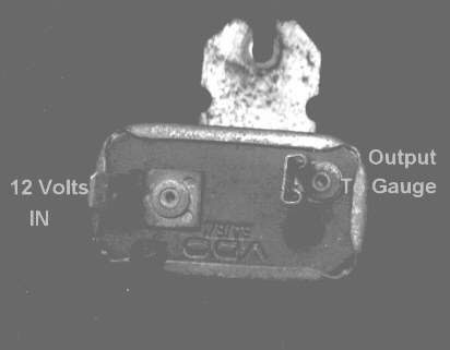
Regulator pinout: photo by Speedy Jim


Now rather than fumble around with my gauge, Speedy Jim has very handy pictures of a disassembled regulator.

Photo by Speedy Jim

There are no semiconductors in the regulator! It is not even solid-state: it is all metallic. The redoubtable Speedy Jim is worth quoting in full:

"... 12V from the battery heats up the heater element and warms the strip.  The thermal mass is small and the strip responds very rapidly.  As soon as it begins to move, the strip causes the contact points to open.  This breaks the circuit and the current ceases.  Now, the strip begins to cool off and bends back to its original shape, closing the contact.  This repeats, over and over.  The result is a series of pulses, each with a voltage of 12V.  When the pulses are fed to the gauge, the heater element in the gauge averages the pulses out.

The closer the pulses are together or of longer duration, the hotter the heater in the gauge will get.  By accurately controlling the pulses, the stabilizer has the effect of regulating the voltage (here, we're talking about RMS or "effective" voltage).  Suppose that battery voltage goes up (as when the generator increases output).  The heater in the stabilizer will heat up more rapidly and open the contact points sooner.  The result will be shorter pulses of 12V sent to the gauge.  The opposite happens when the battery voltage goes lower."

Diagram by Speedy Jim

The diagram leaves no doubt. Far from a humble LM7812, this is a switched-mode power supply. The diagram show a pulse-width modulated (PWM) output at a frequency of 3Hz and duty cycle of 33%. And all this using just metal. It is as if I decapped a SMPS controller IC like the MC34060 and all I found was solder and wire! Compare this to a typical SMPS:

Solid-state SMPS

And you cannot argue with the reliability: I got the Beetle in 1992 and that regulator must have lasted 30 years of steady use, in a harsh environment with lots of vibration and shock. I would have been pleased if a solid-state regulator lasted half as long. Since it is a 1969 model there is a good chance it might have lasted over 50 years.

Now since the switching rate is only 3Hz, it should be visible if connected to a light. Speedy Jim used a light bulb, but these days there are very cheap 12V LED modules, especially if you cut one off a strip light.

12V LED module: just connect directly to the regulator

I unhooked the sender wire and connected it to the LED module. It lit up but did not blink, so there is no switching by the bimetallic strip in the regulator. I ordered a cheap China part for RM28 (USD4) . This would just be a rudimentary solid-state regulator with just a zener diode and a limiting resistor. 

Now I do not recommend connecting anything electrical to the fuel tank much less 12V from a car battery that can potentially deliver 200A, so extreme care is necessary, in particular when you connect up the wires. Note that the current from the regulator is from the 12V car battery and is being limited by the coil in the fuel gauge so we will use that as the power source. Still the following section delivers a 12V PVM signal into the fuel tank potentiometer (as well as the fuel gauge) and there is always a risk of sparks, especially if you move the fuel tank.

But it was still a good 10 days before it arrived, and in the meantime it would be nice to actually produce those PWM pulses if only to see history in action once more ...

L293D Motor Shield for NodeMCU ESP-12E V2
 

I had been working on a WiFi-controlled L293D Motor Shield for ESP-12E NodeMCU and it produces 12V PWM pulses suitable for driving DC motors as well as LED lighting. It runs an Arduino sketch, and you can get a copy from github. 

The key change is to the PWM frequency:

analogWriteFreq(3); /* Arduino v1.8.5 only */

Note the current Arduino reference says that the minimum value is now 100Hz. However I am on an old version, 1.8.5 and I could dial down the PWM frequency right down to 3Hz, so your mileage may vary.

I disconnected the regulator from the sender, and wired up the motor shield thus:

Pinout for VW Fuel Gauge Regulator PWM

The LED module is used to observe the PWM blink rate. You enter your WiFi access point SSID and password, recompile and download the program into the ESP-12E V2, usually via the microUSB port.

You will want to test youe setup driving 12V LEDs instead of the sender. Since you want to connect to the fuel tank at the last possible moment. I set up everything, including the phone browser before I did so. In particular you do not want to accidentally reverse the polarity to the sender, either by miswiring or by using the program's motor reverse command. An LED indicator is better than a filament bulb here.

 Once the  program starts your 12V led module will start blinking at 3Hz. To send a signal to the fuel gauge, you use a browser (I used Google Chrome on my Android smartphone) and type in:

http://12.34.56.78:8080/pwm1/33

And the fuel gauge immediately started registering the petrol level in the tank. This is because the L293D produces a 3Hz pulsetrain at 33% duty cycle, just like Speedy Jim said.

And you can produce a zero fuel reading by:

http://12.34.56.78:8080/pwm1/0

A full tank reading is

http://12.34.56.78:8080/pwm1/100

And not wanting to push my luck, I took down the setup as soon as I could. 10 days after, the new regulator arrived and the VW fuel gauge was fixed. I kept the faulty regulator: it is a reminder that SMPS is a lot older than solid-state electronics.

Root cause: the heater element appears to have disintegrated so the regulator is stuck in the 'On' position and failing to switch off


Happy Trails.


Monday, 26 December 2022

Small DC/DC UPS


5V to 5V DC UPS

Backup time is approximately 1 hour using 3000mAh 18650 battery. Or, you can get a proper UPS Hat like this one:

UPS Hat with Raspberry Pi (bottom)


It is very tempting to make a UPS from generic lithium battery chargers, especially if you just want to power devices like your internet modems and WiFi. And some power banks can be recharged as well as output power at the same time. A few can have their input power turned on and off without dropping their output, just like a UPS. But there are problems: often the power bank heats up. 

It seems lithium batteries may not like to be float-charged. A common lithium charger IC like the TP4056 measures the current supplied to the battery and turns off charging when it thinks the battery is full. Diverting part of this current to supply the load at the same time interferes with this and may even cause the charger to fail to stop charging the battery. The latter may heat up. In particular lithium polymer batteries may swell up burst or pop its enclosure. Dr. Gough's has an excellent writeup on the subject.

Lithium Polymer Battery

It is safer to use the bulkier lithium ion protected 18650 format, with safety vents, and extra overcurrent and overtemperature circuits. They are often slightly larger the the unprotected ones.

Typical Protected 18650 battery

Another thing to look for is the metallic strip or tab running from one end to the other.

Note the conductive strip running vertically down the 18650 protected battery on the right


18650 batteries are also easy to replace if mounted in holders. They are also surprisingly economical.

18650 are not AA size batteries


The despite its name the Geekworm UPS Hat for Raspberry Pi is NOT a UPS. My battery swelled up within days running as one. It works perfectly well if the Hat was charged with Pi turned off. Note a Pi when shutdown via software still draws 100mA.

The late unlamented Geekworm UPS Hat V1.0

CAUTION

It is generally NOT ADVISABLE to repurpose generic lithium chargers as UPS, Especially using no-name TP4056-based chargers like this one! Lithium battery-based UPS need to be designed for that purpose. When charging your batteries, you generally do not turn on the load. When the load is connected, the charger is not. Do not leave this setup unattended - there is risk of fire. I am also assuming you are familiar with electronics and its attendant hazards. The purpose of this project is to exercise your electronics chops i.e., to get some insight into lithium battery UPS design issues. This is NOT a viable design. 

Having settled on the 18650, I happened to have this no name 'TP4056 Lithium Battery Charger with Protection' board in my parts bin. The PCB was marked '03962A' and there is even a schematic.

The deliciously cheap 'TP4056 Lithium Battery Charger with Protection' 

 
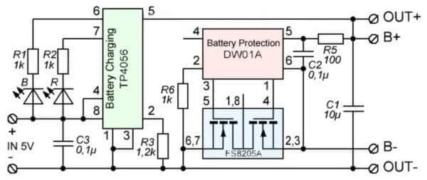
Schematic for 'TP4056 Lithium Battery Charger with Protection' 

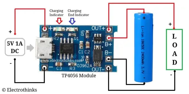
 A straightforward connection as a UPS might look something like this. 

Wiring diagram from Electrothinks

The UPS battery will switch over and back very quickly if the charger drops out or in. The problem is the red charging indicator will not go off as long as the load is also present. And this will result in the 18650 with a somewhat shorter service life.

Now if I add 2 schottky diodes thus, the TP4056 Charger will turn off charging with load connected:


The problem is when running from battery the output is just 4V maximum, too low for the Raspberry Pi. Luckily I have on hand a cheap and cheerful MT3608 DC-DC Boost Converter:

MT3608 DC-DC Boost


 The resulting schematic is:


Battery output boosted to 5V using an MT3608

Note you have to adjust the the MT3608 output before you connect the load. While these generic boards generally work, the quality of the assembly can be a little variable, with dry joints or bent pins. A bent pin in the variable resistor can result in an output of over 20V!

There are quite a few inadequacies: the input 5V to the charger needs to be steady, between 7V-4.6V. Too high and the TP4056 will be damaged. Too low and it will fail to forward-bias the schottky diode and cause the load to be supplied from the battery which means the charger will not switch off and the battery may overheat with continous use. 

This is a little problematic as a UPS is supposed to tolerate a wide variation in input voltages. In my case my 5V is supplied from a mains 5V 2A adapter which works for me. You need to re-test when you change to different input 5V sources or loads. In my case a Raspberry Pi Model B draws different loads depending on use of dongles; even plugging in the Ethernet connector will increase draw.

Happy Trails. 


Saturday, 25 December 2021

Philips 9W LED Lightbulb Repair


Philips 9W LED lightbulb, with plastic cover off

For the first 40 years or so of my life lightbulbs were not repairable: you just threw them away. So when the living room lamp bulb went dark this Christmas afternoon, I had a bit of a lightbulb moment: lightbulbs are LED these days and perhaps they can be repaired! 

The 'bulb' was simply a plastic dome, and had to be pried off. It was just glued on without the need of a hermetic seal. Just one LED, LED3 was blown as since all the LEDs are connected in series, the entire string now no longer worked.

LED3 (bottom center) had a crater in it and fell apart the minute it was touched.

The repair was simple: I just bridged LED3 contacts with solder.

LED3 solder-bridged

And it works!

Repaired lightbulb. Notice the dark spot missing an LED at far left of LED ring

I decided not to install the plastic cover: that will help compensate a little for the reduced light from the missing LED. But of course, hazardous voltages are now exposed. Which is why I installed it in my soldering station lamp, which is nearly entirely covered and out of harm's way:


Toolboom has a great article on LED lightbulb repair; do check it out. I had bought just one smart lightbulb, not wanting to throw out a bunch of electronics just because the bulb is faulty. Do not just bin your faulty IoT devices: they have to be physically destroyed as the electronics can be a security risk. Now that they can be repaired, it would be fun to hack a bunch of faulty bulbs. 

Have yourself a merry little Christmas. Happy Trails. 

Frank Sinatra- have Yourself A Merry Little Christmas


Friday, 24 December 2021

Hacking the Hitachi RAC-EJ10CKM Air Conditioner Remote


Hitachi RAC-EJ10CKM and IR Remote

Most of the Internet of Things (IoT, ie smart home) work on new products, new dimmable color LED lightbulbs, new robot vacuum cleaners, cameras, toasters and the like. To get a reasonable degree of intelligence in a smart home requires considerable financial investment. 

And yet there are serious issues that discourage such an outlay. Issues like computer security, reliability (especially those based on WiFi), inter-operability problems, and vendor lock-in. Google products rely on Google servers, and they can fail. Being locked out of your house by a smart lock is extremely annoying. 

Perhaps one way of encouraging IoT adoption is to lower the cost of entry. Most people already have home appliances;  maybe we should retrofit IoT to existing appliances, like smoke detectors, listen for unusual noises like door/window opening, dogs barking and thunder. Or monitor the oven; a 'Hey Google, there's a chicken in the oven' function would be nice. But let us start with the easy ones, some low-hanging fruit, air conditioners.

I have always wanted to automate my air conditioner: it would be nice not to worry about leaving it on by accident. I usually need it for just an hour or two until I fall asleep; it would be nice to have it take an input from a sleep tracking sensor. Or having a passive infrared turn it off when there is nobody in the room. Most air conditioners seem to be controlled from a infrared remote: perhaps I can get an ESP8266 to transmit the control codes. There are quite a few Arduino projects hacking AC remotes, like this one from TaxeIT, whose source code is here. 

Unfortunately my Hitachi seems to be  one of the few exceptions. I could capture the control codes, but the AC stubbornly refused to respond. Yet TaxeIT's method worked well with my Toshiba TV remote. Perhof seems to have an answer: the Hitachi code is simply too long! Perhof uses code from Analysir and my copy (tweaked to use GPIO14) is here. It is nearly the same except for a little tweak for the ESP8266:

void ICACHE_RAM_ATTR rxIR_Interrupt_Handler() {

The resulting capture fires are in my github repository. It helps to check the length of the capture file from each button press:

$awk -F"," '{print NF-1}' AC_On_Raw.txt
530
$awk -F"," '{print NF-1}' AC_Off_Raw.txt
537

This is markedly longer than the files from TaxeIT:

$awk -F"," '{print NF-1}' hitachiACon.txt
98
$awk -F"," '{print NF-1}' hitachiACoff.txt
98

The bigger files have minimum memory requirements, which may be awkward for some CPUs, but fortunately the ESP8266 was more than adequate. Analysir's tutorial has the code to transmit large files. Note the raw capture files have alternating positive and negative numbers, but the transmit code expects all to be positive. This is easy enough to do:
$sed 's/-//g' AC_On_Raw.txt > AC_On.txt
$sed 's/-//g' AC_Off_Raw.txt > AC_Off.txt

And the codes can then be read into the sendRAW_Flash.ino with a little bit of editing. This worked first time if I hold the transmitter no more than 1m away from the Hitachi air conditioner IR remote receiver. Note that throughout, my hardware is still from TaxeIT, reproduced here for convenience:

Image from TaxeIT

Schematic from TaxeIT

There you have it, a proven hack for the Hitachi RAC-EJ10CKM  IR Remote.

Happy Trails.

Thursday, 23 December 2021

Remote Control of Hitachi RAC-EJ10CKM Air Conditioner


NodeMCU ESP-12E with Baseboard and IR transmitter. The clothes peg is used to hold the IR LED in place aimed at the air conditioner

I have often worried about leaving the air conditioner on when I am out of the house, so being able to remotely monitor and control it seemed like a good idea. Using its infra-red remote link seemed like the natural way. 

The go-to method would be to buy a spare remote and wire an ESP8266-based WiFi relay to the On/Off button, but just for kicks I thought it might be fun to hack the 38kHz remote datalink itself. That is the subject of another post, but having hacked it, I now need to transmit the On/Off code to the  air conditioner's indoor unit. 

As usual someone, in this case TaxeIT has beaten me to it. The relevant circuit here is the IR transmitter using an ESP8266 output pin to drive an IR LED via a 2N2222 transistor. I ripped an IR LED off an old DVD Player remote, and my power adapter is 9V DC from a long-dead ADSL modem. For ease of installation, the aim was to be able to park the transmitter as far away as possible and still reliably switch the air conditioner. I managed 2 metres; the Hitachi remote easily did 4 metres. My circuit is:

38kHz IR Transmitter Circuit

The is a good writeup on driving IR LEDs by 'E' here. I was probably a little conservative with my unknown LED for 'E' drives his IR204 at 200mA. The IR204 has a maximum continous current rating of 100mA but a peak current of 1000mA. Since the LED is only transmitting for milliseconds, this is probably OK. 

Bear in mind my circuit is for convenience only; I happened to have a nodeMCU baseboard V1 for my ESP-12E which lets you use up to 12V at the input. There is nothing wrong about using 5V and dispensing with the baseboard like TaxeIT. One of the advantages of 9V or higher is I have more headroom to drive more than one IR LED in series. Angling each LED in slightly different directions will greatly ease the problem of lining up the transmitter with the air conditioner receiver. Try not to overdo it: if there is more than one air conditioner, you might then accidentally switch the wrong one. 

The other reason to use a baseboard is it is easily powered by a battery or power bank, which makes it a lot more convenient to check out the possible installation points.

The decoded remote data is something like

const unsigned int HitachiAC_On[] PROGMEM = {3378, 1696, 448, 1255, 448, 398, 471, 398, 470, 398, 470, 399, 471, 397, 471, 399, 471, 406, 470, 398, 470, 398, 470, 398, 471, 397, 472, 1255, 449, 398, 471, 398, 471, 404, 471, 398, 470, 397, ....

Note that despite the Hitachi using the same button for On/Off, it sends a different bitstream on Off:

const unsigned int HitachiAC_Off[] PROGMEM = { 189, 63402, 2071, 133, 141, 79167
0, 3447, 1621, 512, 1189, 512, 355, 512, 355, 513, 354, 512, 355, 512, 355, 513,
 356, 512, 362, 513, 354, 513, 354, 513, ...

Which are simply timer intervals to alternately turn the LED on and off. The hack was a little difficult as the bitstream turned out to be unexpectedly long. This is apparently true of some of the Hitachi models. The ESP8266 Arduino code is based on IRremote, with a pretty good explanation here. The source code is in github.

To turn the air conditioner on, I use either http or MQTT. For http I use curl:
$curl --connect-timeout 2 -k http://12.34.56.78:8080/on
<!DOCTYPE HTML>
<html>
Aircond is on</html>

To use it with the MQTT server:
$mosquitto_pub  -t 'aircond/commands' -m 'StudyAC_On'

The MQTT server is typically started on power-up with something like:
$mosquitto -c /etc/mosquitto/mosquitto.conf

This works well as long as the transmitter is not more than 2m away and pointed directly at the Hitachi air conditioner, ie at the IR receiver in the bottom right corner. However, the command might be ignored if say the air conditioner is already on and the 'On' command is transmitted. This happens if for example someone else operated it via its regular IR remote. Worse if the WiFi command is used sometimes curl times out without completing the command. This happens especially when there are WiFi connection problems.

To resolve lingering doubts about failing to turn off the unit, I use a separate IoT system, a Raspberry Pi to visually detect the orange 'On' LED on the indoor unit. Now that seems like overkill, but that Pi can be to detect other events remotely like smoke detectors, thunderclaps, door bells, distress calls, etc. At some point. With a lot of programming. But you get the idea ... I integrated it into my Google Assistant smarthome server for the remote operation part. 

Here is a video of it in operation:

Youtube video of voice activation


There you have it, a remote controlled Hitachi air conditioner, an IoT air conditioner.

Happy Trails.

Tuesday, 7 December 2021

Did I leave the Air Conditioner On? Indicator LED detection using Raspberry Pi and OpenCV


Air Conditioner Indoor Unit with Yellow Indicator LED

Air conditioners are essential in hot and humid Malaysia, especially if you want to work from home. Most of us have occasionally wondered if we have left it on after we left the house: the resulting electricity bill can be a nasty surprise. Most times you cannot do much about it, save for going back home to check.

But then, I managed to hack its infrared remote using an ESP8266, which made it an Internet of Things (IoT) device, which lets me turn it on and off from my smartphone. Now I have a need to know if I left the aircond turned on at home.  

When the indoor unit comes on, there is a beep and an orange LED lights up. The standard way is to mount an optocoupler diode in series with the orange LED, wire the optocoupler output to an ESP8266 and the resulting IoT will reliably report the aircond on/off status every time.

But variety, they say, is the spice of life, and I happened to have an obsolete Raspberry Pi Model B with OpenCV installed. And lots of ancient 640x480 webcams. Granted the lighting conditions would change through the day, but surely it can recognize that round orange light with some consistency?

USB webcam looking at the indicator LED from 3 feet away

It would be a bonus if software can be added later to detect that beep. That would have other applications like detection of smoke alarms' beeps, thunder, doorbell chimes and other interesting sounds. But that is another blog post.

OpenCV Raspberry Pi Model B with LAN connection (ie 'headless' mode)

 Isaac Vidas looks like a good starting point, first using an HSV transform to isolate the color of interest, then using cv2.HoughCircles() to precisely locate the LED itself. 

Image after HSV transform

I did need some additional help in setting the color thresholds required in his code to:

# Get lower orange hue
lower_orange_hue = create_hue_mask(hsv_image, [0, 0, 255], [0, 255, 255]) 
# Get higher orange hue 
higher_orange_hue = create_hue_mask(hsv_image, [0, 0, 255], [38, 255, 255])

There is a handy python script by nathancy here, and together with a HSV color wheel, my threshold values could be determined using several images of the aircond LED under different lighting conditions.

HSV Color wheel


Image after color filtering


Firstof, you will be needing a programs to view the USB webcam video and still frames. I use mplayer and feh:

# apt-get install mplayer
# apt-get install feh

You set the Pi via raspi-config not to run the X Server (ie the GUI desktop), but it helps to have the X libraries installed. From your laptop/desktop you just ssh in:
fred@pi:~ $ ssh -t -Y 12.34.56.78

And from there, mplayer should display the video on your desktop. This lets you position the camera properly.
fred@pi:~ $ mplayer tv://

To get 10 still frames after 10s (some cameras auto-adjust brightness):
fred@pi:~ $ mplayer -vo jpeg -frames 10 -ss 10 -brightness 25 tv://

You can use 'mplayer -loop 0' to display the still images, but they flash on and off rather annoyingly. I much prefer something like feh:
fred@pi:~ $ feh .images/image_on.png

And best of all, the openCV code will execute as if you were using the Pi's console (ie HDMI).

Having selected your camera position, you should probably make a set of images under different lighting conditions. I used a fragment of Isaac Vidas's code to do this, in particular to see the effect of lighting on the separate operations like blurring and HSV transformation. This is named webcamTest.py and is available on my github repository. You typically do:
 
fred@pi:~/checkLed $ source ~/opencv/OpenCV-4.0-py3/bin/activate
(OpenCV-4.0-py3) fred@pi:~/checkLed $

(OpenCV-4.0-py3) fred@pi:~/checkLed $ python ./webcamTest.py image_on.png 

Next, use the nathancy code, which I named hsvThresholder.py. 
(OpenCV-4.0-py3) fred@pi:~/checkLed $ python hsvThresholder.py

hsvThresholder.py: adjust the sliders at the bottom. Runs very slowly on a Pi B, so be patient and watch the console output in the window below

You want to adjust the various sliders in order to mask out all other regions of different color to your LED. A Raspberry Pi 1 Model B will be extremely slow here so patience is required. One way is to watch the bash console messages as they are much quicker to update than the picture. Copy the final settings from the console, which will be something like:
(hMin = 0 , sMin = 0, vMin = 85), (hMax = 28 , sMax = 255, vMax = 255)

My version of Isaac Vidas's code is named checkAC_led.py. and pretty much works as advertised, except it required a much larger (something like 6x diameter) image of the LED. I would have needed to mount my camera much closer, just 17cm from the LED. The other problem is the camera needs to be square over the LED as cv2.HoughCircles() do not detect ellipses very well. And line (ie hollow) circles worked better than a solid one.

Image with test circle added: this is the minimum size circle cv2.HoughCircles() will detect

Mounting my camera closer and square-on the LED is the correct solution. This also minimizes false alarms and improves reliability of detection. This probably means some sort of mounting bracket on the wall, and might get in the way when the air conditioner is being serviced. A software solution would be great, and the future beep detector would help filter out those false alarms ...

This led me to cv2.SimpleBlobDetection() code, which does much better with smaller and deformed circles. Take care to set minArea as large as possible: I actually counted the number of LED pixels in my HSV transform.

The gotcha here is that the HSV image has to be inverted for blob detection to work:
    h, s, image_gray = cv2.split(full_image)
    image_gray_neg = cv2.bitwise_not(image_gray) 
    detector = cv2.SimpleBlobDetector_create(params)
After conversion to grayscale and inversion

After successful blob detection


The final version, checkACvideo_led.py reads from the webcam instead of still image files, filters out false alarms based on the blob x and y coordinates and prints the air conditioner status. In its IoT form the print statement just needs to be modified to publish to an MQTT server like mosquitto.

So did I leave the air conditioner on? Hey Mycroft, is my air conditioner on or off?

Happy Trails