Wednesday, 4 March 2020

IoT Home Alarm: A New Beginning

Active House Alarm: Malaysian street-dogs are very territorial and alert 


Over the years I have been working on and off on my Home Alarm system, always upgrading it but never quite happy with it. I did arrive at some thoughts for a good alarm, which are:

  1. It is not always ideal to catch the intruder. In the suburbs a break-in is often done by someone familiar with the neighborhood. Often he is a neighbor, a relative/friend of a neighbor who visits or house-sits. The penalty for a first offense break-in is only a few months incarceration, and after it is over, guess what, he is still your neighbor except this time he hates you. Deterrence is a better goal for a home alarm: how to convince a prospective intruder to burgle elsewhere. Even if the system gets a positive ID on the intruder, it is often better to pop a printout of the offender into his letterbox: the prospect of jail-time is is a much better deterrence.
  2. The best deterrence is a concerned neighbor who investigates the alarm, sticks his head out the window, turn the light on, or somehow lets the intruder know the jig is up. He should not intervene or confront the bad guy, just the prospect of a call to the police is often enough. Of course, if your immediate neighbor is the bad guy then you have a big problem.
  3. It then follows that a good alarm should have minimal false alarms: you do not want to annoy your neighbor, and worse, condition him not to investigate.
  4. A successful burglary often means he will come back. He already knows the layout of the house, mode of entry, as well as the payoff.  
  5. There is no such thing as a perfect alarm system. Determined intruders will always find a way in. The key goal is to convince them to go elsewhere. Like that Asics jogging shoes ad, when confronted by a lion it is sufficient just to outrun your companion. 


Asics running shoes ad
The features of a reasonably effective home alarm should then be:
  1. Able to identify the intruder. This usually means high-resolution cameras with good lighting. It is a problem if he is masked, so they should also cover the driveway to identify the getaway vehicle. Ideally a light source just behind the camera should switch on. It is instinct to look at the light: you then get good face shots. There is nothing more annoying than camera footage which almost IDs the intruder. To minimize false alarms the camera should not trigger the siren. 
  2. Able to raise the alarm. A siren is often enough. It should not go on for more than a few minutes: few intruders will hang around that long. The ones that do: well you probably don't want your neighbor to mess with them. Sensors that trigger the siren should be door or window switches, indoor passive infrared sensor, drawer micro-switch, etc. 
  3. Notify you when offsite. This lets you review the sensors and perhaps call for help.
  4. Do unexpected things. Popular commercial alarms behave in well-known, and hence predictable ways to knowledgeable intruders. Especially the sound of a snarling dog - the prospect of immediate personal injury is quite distracting. Just make sure it is not played too long. It is best not to install booby traps (paintball gun is my favorite) - they almost always catch the house occupants at some point.  
The good news is current IoT developments bring exciting new capabilities. Even inexpensive IP cameras come with motion detection and some ability to recognize humans. This is especially useful when sifting through hours and hours of security footage. Intruders often do quick surveys from  outside; so a good deterrence is posting a printout of them doing just that. A bonus is you get confirmation of online purchased deliveries. 

Smartphone Apps now allow the alarm to contact you remotely. And best of all, wireless sensors remove a major disincentive to alarm installations: expensive and often unsightly wiring. 

Best of all the IoT parts required are cheap and getting cheaper. So it is time to make a start. And a good start is a passive infrared (PIR) sensor linked directly to a siren. This way I can incrementally add to the system without needing to take it down for upgrades.

The HC-SR501 cost me only RM5 (about USD1). Note the range and delay adjustments are especially handy
The HC-SR501 PIR sensor costs only RM5 from Cytron. The HC-SR505 on the other hand was less useful as the range is a little short and not adjustable. And the price is not much different.

HC-SR501 Schematic


You can pretty much hook up the HC-SR501 directly to a siren via a relay module

The HC-SR501 can be used to directly trigger a siren. But adding an ESP8266 will let the siren be triggered by other sensors in the future. And little conveniences like alarm arm/disable functions from the smartphone.

1-channel ESP-01S Relay Module, shown with ESP8266-based ESP-01S installed

This 1-Channel ESP8266-based ESP-01S Relay Module is slightly problematic when used with an ESP-01S (see my post on this). However it can be used unmodified with the NodeMCU ESP-12E. This relay module is not to be confused with the Diymore Serial 1-channel ESP8266 Relay Module, which has an onboard CPU and is triggered from the serial port rather than a GPIO line:

Serial TTL 1-Channel ESP8266 Relay Module, with ESP-01S mounted

I found the ESP-01S a little problematic getting the GPIO lines to work as input, so for this build I used the NodeMCU ESP-12E instead:


ESP-12E NodeMCU development board, with CH340 USB interface

Wiring Diagram
The wiring is, from the point of view of the ESP-12E:
GPIO13 - Relay control line
GPIO12 - PIR output
The assembled system looks like this:

Left to right: USB power connector, NodeMCU ESP-12E, 1-channel ESP8266 Relay Module and HC-SR501 PIR sensor
You connect your siren to the relay contacts. This lets you switch most sirens, from mains powered sirens, 12V automotive car horns or a more discreet 5V buzzer. Personally, I find the 12V automotive siren plenty loud and easy to back up with car batteries.

12V Siren


As usual there is a sample program in github.  The program creates a WiFi access point, "SirenAccessPoint". and you log into it using your smartphone. You then type into your favorite browser:
http://192.168.4.1/arm           to turn the alarm on
http://192.168.4.1/disable      to turn the alarm off
http://192.168.4.1/sirenon      to turn the siren on
http://192.168.4.1/sirenoff     to turn the siren off

As a start the system does not assume you have a WiFi infrastructure, and you can pretty much move it to any location you want to protect. One caveat is many PIR sensors are triggered by direct sunlight, so your mileage will vary.

By having other devices to log into the AP, we can now trigger, disarm or mute the siren using the same http messages. However a true IoT system needs a way to contact your smartphone offsite. For that we will be needing some kind of communications infrastructure, usually an MQTT gateway. For simplicity, later iterations of this project will use WiFi broadband, as with the other IoT projects in this blog.

There are many things to add: door magnetic switches, IP cameras, motion detectors and lighting control. But there you have it: a cheap DIY House Alarm to start you off. 

Nightwatch


In the meantime, I have a pair of rescued Malaysian street-dogs on duty round the clock, and honestly, that IoT Alarm System has a lot to live up to.

Happy trails.

Tuesday, 28 January 2020

Hacking the HW-655 ESP8266 WiFi IoT Relay Board

HW-655
I got my HW-655 for just RM10, ESP-01S included. However it did not work and I suspected the seller just plain forgot to program the STC15F104W CPU. Luckily, Sergiy Zaschipas has a great writeup on this and I strongly recommend a careful read.

[2020-07-12 update: here's the hack for the 2 relay Nuvoton N76E003 CPU version]

I had always wanted to reprogram these serial relay modules. They are perfect for use with the ESP-01S. When reprogrammed a number of them can be daisy-chained on the same serial port allowing a single ESP-01S to control them all. They can also be daisy-chained without reprogramming, but then all the relays would turn on and off at the same time.

The same serial port is brought out to a header and this also lets a Raspberry Pi control the relay daisy-chain with a minimum of wiring. The usual hat is maybe the Piface Digital or Piface Digital 2, but of late Piface libraries has been buggy and it has begun to feel like abandonware.

So hie you hence to Zaschipas' repository. There stays a program to make you a working HW-655. Since I mostly run Slackware, I would add a few notes. sdcc, the compiler for the 8051 CPU (STC15 is an Intel 8051 derivative) is installed thus:

$tar -xvjf sdcc-src-3.9.0.tar.bz2

But you will first need gputils:
gputils-1.5.0$./configure
gputils-1.5.0$make clean
gputils-1.5.0$su -c "make install"

Then to sdcc proper:
sdcc-3.9.0$./configure

The compile takes a long time so if you have the resources to run it in parallel, I would recommend:

sdcc-3.9.0$make -j 10
sdcc-3.9.0$su -c "make install"

If you do not want to compile Sergiy's relay.c from source, here are my results:
$cat relay.ihx
:0400000002001132B7
:03000B0002012CC3
:03006A0002000E83
:03000E0002006D80
:20006D0075415575425075B10075B204C2B2753B00753D00C20412019BE4F53FF540E53F55
:20008D002441F9E7FF600F8F8212018F053FE4B53FEC054080E810030302011985223CE53E
:2000AD003B24FC5003020119E53B75F003A49000BF730200CB0200D40200E20200F974A0E5
:2000CD00B53C49053B80457401B53C04053B803C753B0080377401B53C028004E53C700783
:2000ED00053B853C3D8025753B00802074A2B53C0B7401B53D06D2B2D204800D74A1B53C54
:20010D0008E53D7004C2B2D204753B001004030200A3A2B2E433F58212018F0200A322C073
:20012D00E0C0D0300120D52628752603D52809852422C201D2038019E524C313F52430B056
:20014D0010432480800B20B008D201752604752809D52529752503300023E527700AC2B114
:20016D008521237527098015E523C313F523D52708D2B1C200D2028004A2D792B1D0D0D0AC
:20018D00E032AF8210020280FB8F21D20022759850C2AFC2B9C2A9C28C758900758E8075E4
:1C01AD008A80758CFED28CD2A9D2B9D2AFC200C201D202C20375250075260022D3
:06004000E4787FF6D8FD14
:20001E007900E94400601B7A009001CD780175A000E493F2A308B8000205A0D9F4DAF275BA
:02003E00A0FF21
:200046007800E84400600A790175A000E4F309D8FC7800E84400600C7900900001E4F0A3B8
:04006600D8FCD9FAEF
:0D0011007581421201C9E582600302000EF4
:0401C9007582002219
:00000001FF

The utility to program the STC15 is stcgal and I installed it thus:

$pip3 install stcgal

Getting stcgal to program was very tricky. I used a CH340 USB to serial ttl dongle set for 3.3V.

CH340

What worked for me was to run the CH340 and the HW-655 from separate 5V power supplies, the latter seemed to work better from  battery-power, like from a power bank. Unusually, I had to connect the CH340 TX to HW-655 TX and RX to RX (you usually connect TX to RX), but your mileage may vary. You then ran the programming command; mine is slightly different from Sergiy's:

Programming setup: CH340 in center and the 1-channel serial relay module on top. Wires are TX-TX, RX-RX and GND-GND


$stcgal -p /dev/ttyUSB0  -b 1200  -D relay.ihx

To test, the python interpreter makes it fun and easy:
$python                     
Python 2.7.16 (default, Apr  3 2019, 21:30:55)
[GCC 8.3.0] on linux2
Type "help", "copyright", "credits" or "license" for more information.
>>> import serial
>>> port = serial.Serial("/dev/ttyUSB0", baudrate=9600, timeout=3.0)         
>>> relON = [0xA0,0x01,0x01,0xA2]
>>> port.write(serial.to_bytes(relON))
4

To use it with the ESP-01S, I need an Arduino IDE sketch. And it worked first time, just like that. The baudrate is 9600. The code repository is in github. To turn on the relay you use a browser with the URL:
http://ww.xx.yy.zz:8080/1/on

You can pick up the device IP address from your router but I used the 'Tools->Port' sub-menu in Arduino IDE which lists the device IP address.

In my installation, the ESP-01S often had to be reset when it has WiFi disconnects and when you use it to control relays this annoyingly resets the relay as well. I can probably flash the relay state into ESP8266 filesystem, but this tends to wear out the flash memory. But the great thing with having a separate CPU like the STC15 is that the relay state is still preserved in there. Except now you need a command to read the relay state back.

First we need to decode the relay commands used. They are:

0xA0, 0x01, 0x01, 0xA2 to turn on a relay
0xA0, 0x01, 0x00, 0xA1 to turn off a relay

Notice the STC15 replies with a 1-byte reply with the actual state of the relay control line.
For modules with two relays the commands for the second relay are:

0xA0, 0x02, 0x01, 0xA3
0xA0, 0x02, 0x00, 0xA2

My guess would be the first byte A0 is the header to indicate the start of a command packet. Next byte would be the relay number, and the third byte would be relay operation code, ie 0 for off and 1 for on. The last byte would be a checksum, which is just a straight sum of the preceding 3 bytes.

So for my relay daisy chain, I would extend the commands as follows for relay 3:

0xA0, 0x03, 0x01, 0xA4 to turn on relay 3
0xA0, 0x03, 0x00, 0xA3 to turn off relay 3

And so on. Now for the relay state read I would propose a new opcode 2, so to read relay 1:

0xA0, 0x01, 0x02, 0xA3

And the answer would be in the same 1-byte reply. I implemented this in the relay_read.c program. To read the state from the ESP-01S I would use a browser and the URL:
http://ww.xx.yy.zz:8080/1/read

For installations were hazardous voltages in the relay module need to be completely enclosed, an external ESP8266 with TTL Serial Adapter PCB may improve WiFi reception


There you have it, an HW-655 in the palm of your hand. Happy trails.

Tuesday, 21 January 2020

3G Failover using the Huawei B310

Huawei B310 3G router
I first implemented a 3G failover using the TP-Link MR3420, but that had a few problems. It got a little erratic with less than 20 IoT devices connected. When in backup 3G mode the uplink often failed when run for too long and the 3G USB modem then needed to be power cycled. In a thunderstorm 3G reception often got a lot worse. But worst of all I could not alter the failover criteria.

This is because my benighted ADSL service provider Talikom Malaysia plumbed news depths in quality of service. The ADSL connection would get erratic, going on and off within a few minutes. Sometimes there would be an actual ADSL connection but it would not be able to reach the TM gateway and from there the Internet. Sometimes the link simply got slow.

This would sometimes cause the MR3420 to remain in ADSL mode and not fail over to 3G. Worse this sometimes caused it to randomly drop connections to some client WiFi devices. Power-cycling it usually helps, but the random dropouts are nevertheless annoying.

Huawei B310 with external antennae


The Huawei B310 has a simple failover criteria: it needed its WAN input cable disconnected before it goes into 3G mode. I could do that with an electromechanical relay; this allowed me to make a custom failover program to handle TM's myriad failure modes. Also the B310 has two connectors for 3G external antennae which are separately bought. And it does not disconnect clients in either 3G or ADSL mode.

The setup is much the same as before:


The Huawei B310's WAN uplink is taken from the Archer D50 via the DES-100S LAN switch. This allows me to disconnect the WAN link by turning off the DC power to the LAN switch. I do this using a Raspberry Pi Model B and a Piface hat.

Because of frequent electrical storms, the ADSL line can also be disconnected by an AS3935 lightning detector relay module.

The Raspberry Pi runs Raspbian. The Piface is controlled by the pifacedigitalio library and the failover program for now is a simple bash script. Here is a first-pass version of the failover program, it did not take more than an afternoon to code and test.

Because of the AS3935 lightning detector, the failover program subscribes to and publishes to a local MQTT server. The piface digitalio library is not one of you best supported ones, but there are a few hints if you run into trouble.

As always the choice of components is not necessarily optimal, if not downright obsolescent. Most of the time they are used simply because they are available on hand. Indeed you can probably get an all-singing all-dancing 3G failover modem router for a very reasonable price somewhere. But it goes against grain not to use working parts simply because they are a little too old.

Much better to go out with your boots on. Happy Trails.

Wednesday, 18 December 2019

AS3935 Lightning Detector: The Sequel

“Look aloft!” cried Starbuck. “The corpusants! the corpusants!"
 "The lightning flashes through my skull; mine eyeballs ache ... " - Captain Ahab

The rainy season came late and in its very first acid test, the AS3935 detected the oncoming storm and disconnected the ADSL modem in good time. However a really close strike after that took out the AS3935's relay module; the lightning must have arced over the open relay contacts into the 5V line. I had unwisely left my laptop connected to it to collect the debug messages, so the lightning took out my laptop as well as its power module, and plunging the neighborhood into darkness.

And to prove it was no fluke, repeated strikes on the now-unpowered system produced white arcs on a twitching relay board, a real sight to behold in the darkness. "The corpusants", like Starbuck said in Melville's 'Moby Dick'. This is probably very risky, so do proceed with caution if you ever have the misfortune to encounter this.


Scorch marks on the relay module

The over-current on the 5V line is such the heat lifted the copper trace right off the PCB.


The surge must have arced over to the nearby 5V pin on its way to the USB power line

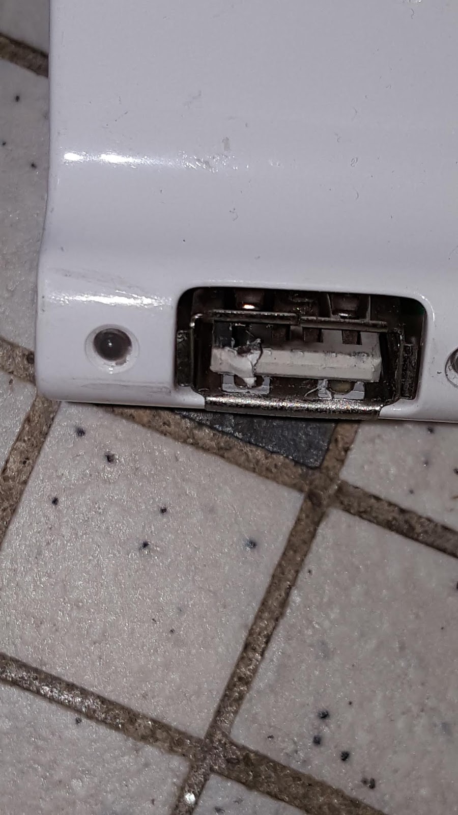
And welded the USB connector to the hub.


The USB hub socket was welded to the cable. Note the melted contact on the left.
The ESP-12E had no obvious signs of damage but was unresponsive. Happily the AS3935 was undamaged.


Burst mains 'Live' wire in the power extension cable

The 'Live' wire in the mains power extension (to laptop power adapter) open-circuited, although the 13A fuze was intact. The 3A 230V fuze in the laptop adapter blew. This calls for a rethink:
  1. the relay contacts need to be a lot better isolated from each other
  2. more isolation is needed between the relay module and the ESP-12E
  3. the power modules need to be better isolated

(Update 2020-01-22): The lightning strike propagated along the 5V rail and damaged the LM1117-3.3 regulator in the ESP-12E. It also seemed to have slightly damaged the AS3935 (which also takes 5V directly to the IC) and although its registers read normal and it can be calibrated, it no longer classified 'disturber' events as lightning, no matter how near. New parts have been ordered - this is not over!

(Update 2020-02-15): Dismantled my laptop, an Asus X751L. 


Asus X751L disassembled - one of the worst things about laptop repair is the disassembly. There are myriad flimsy plastic tabs to break and also various irreplaceable flexible cables to rip off by accident
As suspected, the fuses had blown:


Blown fuses, middle, just beside the 6-pin 19V power adapter connector. The power MOS QM3024M3 are the square 8-pin IC just to the left
The fuses lead to the drain of a QM3024M power MOSFET rated at 30V and a stonking 46A. The source is connected to a second QM3024M3, and this second MOSFET has a short-circuit from drain to source. Ouch.

The first MOSFET is likely used to turn on 19V from power adapter to the mainboard power supply unit, and the other MOSFET to connect the battery when there is no mains supply. The short-circuit means that the lightning strike short-circuited the 19V adapter output and battery output simultaneously to 0V. Indeed the battery was completely drained. Looks like I have a dead power MOSFET as well. 

Dead bug: QM3024M3 upside down. On removal the mainboard is no longer shorted


I confirmed this by de-soldering it from the mainboard.

Watch this space. Happy Trails.

"... I will do my endeavor. I try all things; I achieve what I can" - Ishmael,  'Moby Dick' by Herman Melville


Monday, 16 December 2019

IEEE 802.11w: Securing your WiFi from Deauth Attack Part 2: Electric Kool-Aid Acid Test


"You are hereby empowered!!!" - Tom Wolfe, The Electric Kool-Aid Acid Test

In Part 1, we tested for cheap devices compatible with IEEE 802.11w-2009. Here, we will just detail the configuration files needed to build a Ieee 802.11w-209 compatible Raspberry Pi 3 B+ WiFi Bridge. The actual steps are detailed in the official Raspberry Pi site.  We will need:
1. Raspberry Pi 3 B+
2. Very good 5V 2.5A USB power module (e.g. the Raspberry Pi 2.5A module). This requirement is important! I used a stonking 5V 6A TDK RDM05-6R0
3. Realtek RTL8812BU generic WiFi dongle. Or a dongle with any of the Atheros chips tested in Part 1.
4. ADSL modem router with wired (ie copper) LAN interface.


For simplicity, the above diagram omits the power supplies and the powered hub. The RTL8812BU can draw a lot of power, especially if connected to an outdoor antenna.

Note it is also possible to set up the above devices as WiFi repeater by using the Raspberry Pi's built-in WiFi chip (wlan0) as WAN.

Top middle: TDK 5V 6A power module. Center: Raspberry Pi 3 B+ with RTL8812BU. Bottom left: thick USB power cable with ammeter showing 920mA current draw

First, set up your ADSL modem and make sure you have Internet WAN access via the copper LAN (ie wired Ethernet). I used a TP-Link Archer D20.

Next, set up your Raspberry Pi 3 B+ with the latest and greatest version of Raspbian. The Linux version of the installation guide worked for me, but there is also a Windows version. It is really worth using a fast sdcard (16GB is sufficient and 32GB is plenty), Class 10 or better if you can manage it.  You will need to set it up to log into your Internet connection. My Pi connected to the Internet when I plugged in the LAN cable. After it has finished installation you need to update it immediately:

# apt-get update
# apt-get upgrade

This can take hours depending on your Internet connection and you will have to reboot your Pi. Next, set up your root password:
# sudo vi /etc/passwd

Remove the 'x' from the line
root:x:0:0::/root:/bin/bash

Next set the root password using:
#sudo passwd root

I usually use the wifi bridge in 'headless' (ie no monitor or keyboard) so I usually turn off the GUI using
#sudo raspi-config

To control it, I usually enable the ssh server (again using raspi-config). Now to run it headless I make sure my laptop is connected to the same network and if it is also running Debian (Rasbian is a version of Debian) I simply do:
$ssh -t pi@raspi.local

It is also handy to have your first setup connected to copper LAN as well as keyboard and monitor, as we will be messing about with networking tools and a mistake is likely to freeze up your remote login.

If wlan1 the rtl8812bu does not come up, refer to Part 1.

Next you will need to stop systemd from messing with your network interfaces.
# systemctl mask wpa_supplicant.service
Created symlink /etc/systemd/system/wpa_supplicant.service � /dev/null.

In /etc/dhcpcd.conf add the lines:
interface eth0
static ip_address=192.168.1.1/24

interface wlan0
  denyinterfaces wlan0
  nohook wpa_supplicant

interface wlan1
  denyinterfaces wlan1
  nohook wpa_supplicant

Reboot, and you should be ready for the next step.

We need to use hostapd for our bridge, so we stop systemd from messing with it:
# systemctl mask hostapd

We make a bridge:
# brctl addbr br0
# brctl addif br0 wlan1

If all went well, you should get:
# brctl show br0
bridge name     bridge id               STP enabled     interfaces
br0             8000.1cbfce5d51a0       no              wlan1

Add the copper LAN to your new bridge in case you want to connect client devices by wire
# brctl addif br0 eth0
# ifconfig eth0 0.0.0.0 up
# ifconfig wlan1 0.0.0.0 up

Where 192.168.1.1 is the IP address of your Pi at eth0 and 192.168.0.1 is the address of your WAN router (ie the D-Link Archer D50 in the diagram):
# ifconfig br0 192.168.1.1 up

Next set up your dnsmasq config file with:
interface=br0
except-interface=lo
listen-address=192.168.1.1
bind-interfaces

As usual you need to tell systemd to keeps its grubby hands to itself:
# systemctl mask dnsmasq
# killall dnsmasq 
# dnsmasq -C /etc/dnsmasq.conf 

Next we get the Pi to start forwarding. Add the following lines to /etc/sysctl.conf:
net.ipv6.conf.all.disable_ipv6 = 1
net.ipv4.ip_forward = 1
net.ipv4.conf.all.rp_filter = 1
net.ipv4.conf.default.rp_filter = 1
net.ipv4.ip_dynaddr = 1
net.ipv4.conf.all.accept_source_route = 0
net.ipv4.conf.default.accept_source_route = 0
net.ipv4.conf.all.accept_redirects = 0
net.ipv4.conf.default.accept_redirects = 0

# sysctl -p /etc/sysctl.conf

Next is hostapd. Set up the config file /etc/hostapd/hostapd.conf thus:
interface=wlan1
driver=nl80211
ssid=ElectricKoolAid
hw_mode=g
channel=1
macaddr_acl=0
wpa=2
wpa_passphrase=VerySecretPassword
rsn_pairwise=CCMP
ieee80211w=2
wmm_enabled=1
auth_algs=3
ignore_broadcast_ssid=1
wpa_key_mgmt=WPA-PSK-SHA256 WPA-EAP-SHA256
wpa_pairwise=CCMP

# killall hostapd
# hostapd -dd -P /var/run/hostapd.pid /etc/hostapd/hostapd.conf -B

Next set up /etc/firewall.conf thus:

*filter
:INPUT DROP [39:4576]
:FORWARD DROP [0:0]
:OUTPUT ACCEPT [42055:10283301]
-A INPUT -m conntrack --ctstate RELATED,ESTABLISHED -j ACCEPT
-A INPUT -i br0 -j ACCEPT
-A INPUT -i eth0 -j ACCEPT
-A FORWARD -m conntrack --ctstate RELATED,ESTABLISHED -j ACCEPT
-A FORWARD -i br0 -j ACCEPT
-A FORWARD -i eth0 -j ACCEPT
COMMIT
# Generated by iptables-save v1.6.0 
*nat
:PREROUTING ACCEPT [78732:17589805]
:INPUT ACCEPT [29742:7228146]
:OUTPUT ACCEPT [2937:514776]
:POSTROUTING ACCEPT [985:97284]
-A POSTROUTING -s 192.168.1.0/24 -j MASQUERADE
COMMIT
# Generated by iptables-save v1.6.0 
*mangle
:PREROUTING ACCEPT [1318452:373291697]
:INPUT ACCEPT [623742:150528221]
:FORWARD ACCEPT [120385:79521689]
:OUTPUT ACCEPT [42068:10285133]
:POSTROUTING ACCEPT [168801:90872517]
-A POSTROUTING -p tcp -m tcp --tcp-flags SYN,RST SYN -m comment --comment "fix packet size for stuff that\'s being routed through this box (SEE NOTE *)" -j TCPMSS --clamp-mss-to-pmtu
COMMIT

# iptables-restore < /etc/firewall.conf

Your IEEE 802.11w-2009 bridge AP "ElectricKoolAid" with "VerySecretPassword" should be up by now.

Over at the client (in my case the Acer Aspire E1) make a wpa_supplicant config file wpa_supplicant.conf. Notice we make IEEE 802.11w compulsory:

ctrl_interface_group=0
eapol_version=1
ap_scan=1
fast_reauth=1

# WPA protected network, supply your own ESSID and WPAPSK here:
network={
  scan_ssid=1
  ssid="ElectricKoolAid"
  proto=RSN  
  key_mgmt=WPA-PSK-SHA256
  pairwise=CCMP TKIP 
  group=CCMP TKIP
  psk="VerySecretPassword"
  ieee80211w=2
  priority=10
}

And, assuming you have already wrestled with systemd (and won!) there too:
# wpa_supplicant -d -Dnl80211 -iwlan0 -c/etc/wpa_SIKAMAT7.conf -B

Note: for some reason, nl80211 worked a lot better than wext

And you should have a working link to the Pi bridge. 

# wpa_cli -iwlan0 status   
bssid=11:22:33:44:55:66
freq=2412
ssid=ElectricKoolAid
id=0
mode=station
pairwise_cipher=CCMP
group_cipher=CCMP
key_mgmt=WPA2-PSK-SHA256
pmf=2
mgmt_group_cipher=BIP
wpa_state=COMPLETED
ip_address=192.168.0.114

And there should be Internet access; provided you have set up your WAN router's dhcp server, the client at the end of the bridge "ElectricKoolAid" should get its dhclient requests routed straight through.

ping -c 4 -I wlan0 8.8.8.8
PING 8.8.8.8 (8.8.8.8) from 192.168.0.114 wlan0: 56(84) bytes of data.
64 bytes from 8.8.8.8: icmp_seq=1 ttl=56 time=524 ms
64 bytes from 8.8.8.8: icmp_seq=2 ttl=56 time=518 ms
64 bytes from 8.8.8.8: icmp_seq=3 ttl=56 time=380 ms
64 bytes from 8.8.8.8: icmp_seq=4 ttl=56 time=346 ms

--- 8.8.8.8 ping statistics ---
4 packets transmitted, 4 received, 0% packet loss, time 3001ms
rtt min/avg/max/mdev = 346.240/442.040/524.243/79.921 ms

To get it to start on power up, just put the commands in /etc/rc.local

There you have it, IEEE 802.11w-2009 AP and client, immune from the dreaded Deauth Attack. In part 3 we will launch an aircrack-ng deauth attack at the the bridge AP.

Or, as Tom Wolfe said: "You are hereby empowered!!!". Happy Trails.

Thursday, 12 December 2019

IEEE 802.11w: Securing your WiFi from Deauth Attack Part 1 - The Right Stuff (Updated 2019-12-31)

The Right Stuff by Tom Wolfe

"No bucks, no Bucks Rogers" - Gus Grissom, The Right Stuff


One of the guilty pleasures of Linux is aircrack-ng,  software tools to -cough- test WiFi security. In the good old days with WEP WiFi passwords you can get a WiFi password within 2 minutes. It was so convenient it was much quicker than getting the password the legal way from your company sysadmin. Back in the day, the best hotspots are for Top Management, people who don't browse or torrent, dictate their emails and think that typing is for secretaries.


aircrack-ng on Kali Linux


IEEE 802.11 is the standard for WiFi networks. Amongst other things it specifies Management Frames, ie data packets sent by both the client and the Access Point to 'manage' or maintain communications with each other, for example, logging in, authentication and when one party wishes to terminate the connection, 'deauthenticate'.

With WPA (in particular WPA2), cracking WiFi hotspots became much much harder, but if the password is weak (most passwords are weak) you can speed things up by getting aircrack-ng to issue 'deauthenticate' Management Frames in your victim's name (ie MAC address). This causes the target to re-issue authentication frames. The more frames you sniff out, the quicker you will crack it.


Now if you do nothing but issue deauth frames, say with a bash script, you effectively jam WiFi for the luckless target, and if you target the AP MAC address you jam the whole hotspot if you are close enough. Normally you did it for a purpose, like persuading the legal users to quit using their WiFi so you can, -cough-  check-in your flight online. People who deauth used to have a higher purpose ... besides it is easy to spot the pasty-faced user on the Linux laptop with an out-sized WiFi antenna.

ESP8266 deauth jammer

But with the advent of Espressif's ESP8266  you can now buy or build a cheap portable deauth jammer that will fit inside your pocket, and now all you have to do is walk up to a hotspot to jam it. And since many security cameras these days are WiFi, an intruder can disable them by just driving up to your gate.

Now having made quite a few ESP8266-based IoT devices, it is time to secure my WiFi from deauth attacks: IEEE 802.11w-2009. With 802.11w, the Management Frame is encrypted and becomes a Protected Management Frame (PMF). This means a WiFi outsider now cannot deauthenticate you with impunity.

IEEE 802.11w stops deauth attack by encrypting the 'deauthenticate' command

Now you would think you can buy a new reasonably-priced IEEE 802.11w-2009 router for home use. After all the standard is 10 years old. And you would be wrong. It is common enough in Big Iron like Cisco or Aruba (one of dear old Hewlett Packard's random name changes) but it is not common in say, a D-Link or TP-Link. OpenWrt is a shining exception, as easy as checking an option in its base distribution. But OpenWrt often only runs on the more expensive models, and then there is the problem of compatibility with WiFi client devices.

The usual culprit would be production cost. As Gus Grissom said, "No bucks, no Buck Rogers". It turned out it is probably a compatibility issue, specifically of encryption, a missing cipher. IEEE 802.11w uses CCMP-128, SHA-256 and AES128-CMAC encryption for Management Frame protection.

To tell if your hardware has The Right Stuff, you need to execute the Linux command 'iw phy', shown here for a no-name WiFi USB dongle based on the Realtek RTL8812BU:

# iw phy
Wiphy phy8
        max # scan SSIDs: 9
        max scan IEs length: 2304 bytes
        max # sched scan SSIDs: 0
        max # match sets: 0
        max # scan plans: 1
        max scan plan interval: -1
        max scan plan iterations: 0
        Retry short limit: 7
        Retry long limit: 4
        Coverage class: 0 (up to 0m)
        Supported Ciphers:
                * WEP40 (00-0f-ac:1)
                * WEP104 (00-0f-ac:5)
                * TKIP (00-0f-ac:2)
                * CCMP-128 (00-0f-ac:4)
                * CMAC (00-0f-ac:6)

And listed under the 'Supported Ciphers' the bare minimum you need is CCMP-128 (note OUI 00-0f-ac:4) and CMAC (OUI 00-0f-ac:6). There is a helpful write-up here. Compare this to the output for the delicious Qualcomm AR9565 from my Acer Aspire E1 laptop:

$iw phy                                                
Wiphy phy0
        max # scan SSIDs: 4
        max scan IEs length: 2257 bytes
        max # sched scan SSIDs: 0
        max # match sets: 0
        max # scan plans: 1
        max scan plan interval: -1
        max scan plan iterations: 0
        Retry short limit: 7
        Retry long limit: 4
        Coverage class: 0 (up to 0m)
        Device supports RSN-IBSS.
        Device supports AP-side u-APSD.
        Device supports T-DLS.
        Supported Ciphers:
                * WEP40 (00-0f-ac:1)
                * WEP104 (00-0f-ac:5)
                * TKIP (00-0f-ac:2)
                * CCMP-128 (00-0f-ac:4)
                * CCMP-256 (00-0f-ac:10)
                * GCMP-128 (00-0f-ac:8)
                * GCMP-256 (00-0f-ac:9)
                * CMAC (00-0f-ac:6)
                * CMAC-256 (00-0f-ac:13)
                * GMAC-128 (00-0f-ac:11)
                * GMAC-256 (00-0f-ac:12)

CCMP-256 and in particular GCMP-256 looks really good. Now your mileage may vary with 'iw phy', as some device drivers are known not to be listed. I had best results with a late model Raspberry Pi (3 or 4) running the latest Rasbian (ie Debian).

You can do an online search for compatibility with this link.

From my very limited survey here in Seremban Malaysia only a minority of WiFi devices on the market supports this. And since some device drivers do not come up in 'iw phy' (in particular deliciously cheap Realteks), in the end I had to take my Linux laptop to my friendly local computer shop and test all 5 WiFi USB dongles models he had. None passed the test; in the end an ancient TP-Link TL-822N v1.1 proved up to the task.

TP-Link TL-W822N. Note only v1 worked, and possibly v2. v3 & v4 have Ralink chips

So did the Samsung Galaxy Note 5, with default setings:

Samsung Galaxy Note 5 will work as IEEE 802.11w client


A very pleasant surprise was the Raspberry Pi 3 Model B Plus' BCM4345:

        Supported Ciphers:
                * WEP40 (00-0f-ac:1)
                * WEP104 (00-0f-ac:5)
                * TKIP (00-0f-ac:2)
                * CCMP-128 (00-0f-ac:4)
                * CMAC (00-0f-ac:6)

Unfortunately the results were spotty. Upgrades to Rasbian caused it to stop working, but subsequent updates should fix this, so watch this space for updates.

And since I meant to link my deauth-proof routers to outdoor antennae I took a chance on the RTL8812BU generic USB dongles, from a hint here. 

Generic no-name RTL8812BU USB dongle also worked, but only as AP and not client/STA
This proved to be the toughest to use, as even my up-to-the-minute Rasbian (Buster) did not come with the device driver for it. The dongles came with driver source code, but cilynx (Randy C Wills) has a much better version here. cilynx's instructions (in README.md) worked very well for my Raspberry Pi 3 B+; I just needed to add in the Makefile

EXTRA_CFLAGS += -Wno-error=date-time

And change 'n' to 'y' for

CONFIG_80211W = y

Perhaps because this is a new driver, the default debug logs are very many and to prevent it from wearing out your micro sdcard, you might want to do:

# echo 3 > /proc/net/rtl88x2bu/log_level

And you are good to go.

In summary the WiFi hardware having the Right Stuff for deauth-proof IEEE 802.11w are:
1. Qualcomm Atheros AR9565 (Acer Aspire E1, Asus X751L)
2. Qualcomm Atheros QCA9377 (Acer Aspire F15)
4. Ralink RT5370 (Raspberry Pi 3 Model B Plus)
5. Realtek RTL8812BU (no-name China USB dongle)
6. TP-Link TL-WN822N v1.1
7. Samsung Galaxy Note 5 (and Fan Edition) as client device. The Galaxy Note 3 does not work.

Seven devices with the Right Stuff, just like the seven Project Mercury astronauts. The next step is to rebuild my WiFi Bridges to comply with IEEE 802.11w. But that is another story. 

Happy Trails.

Update: Removed the D-Link DWA-123 from the list, as it did not work. In the Raspberry Pi 3, weird kernel driver interactions caused the built-in  BCM4345 driver (brcmfmac) to work, but only with a Realtel RTL8188EU device plugged in. The last Raspbian update caused it to stop working so BCM4345 results are still pending

Monday, 18 November 2019

Lightning detector AS3935: Part 3 of 3


Clockwise from top left: ADSL splitter, AS3935 (in vise), ESP-12E, relay module, powered USB hub, modem and POTS analog phone. All blinkenlights are go.


In the last part of this series, the AS3935 detector is hooked up to the ADSL line, and the ESP-12E is programmed to disconnect if there is a thunderstorm overhead. When the storm moves more than 8km away it will reconnect after 30 minutes.

As first mentioned in Part 2, it publishes to a local MQTT server, and also subscribes to it. This is to allow it to disconnect and reconnect the ADSL modem remotely on demand. For the last six months or so my TM Streamyx (now 'Unifi') ADSL2+ line has been unstable; dropping and reconnecting every few hours or worse. This constant failover to 3G tended to overload the TP-Link MR3420. Disconnecting the phone line during the bad periods seemed to give it some relief.

As before, the AS3935 can be quite sensitive to inteference. I ended up using separate shielded USB charger cables for 5V for both the ESP-12E and the relay module. At worst, excessive interference resulted in permanent false alarms for 'storm overhead'.

Also you can reduce false alarms by additional shielding. I partially encased the AS3935 module in a steel vise to stop it triggering when I turned on my fluorescent lights. Do not shield it completely or there will be nothing detected.

Jury-rigged steel vise shield for the AS3935


Connecting to the telephone line


My incoming POTS line has two wires, but a standard US RJ11 phone jack has at least 4. Our benighted Talikon Malaysia uses British standard (BS 6312), but most devices (not phone line) comes in the US RJ11 4-wire format, which is what I used.

Lanshack has a good page on the pinout:


The 4 wires in my RJ11 jacks cover pins 2 to 5 corresponding to Pair 1 and Pair 2. Pair 1, ie R1 & T1 at pins 3 & 4  (ie red & green wires) seem like a good starting point. I took out the modem ADSL cable, ie one with RJ11 jacks on both ends and cut it in two. The red and green cables are easily accessible.

Start with your modem phone cable, and cut in in half 


Modem cable with just Pair 1 reconnected

I verified my guess by reconnecting just Pair 1 and used my modified cable to reconnect the modem to the phone line. My ISP TM (TMnuts for short) uses ADSL2+ and that did not seem to affect my modem operation but your mileage may vary. Since broadband runs at 1Mbps up to 20Mbps changing the phone cables characteristic impedance with discontinuities like connectors and joints might affect it big-time.

Also, it would be wise to hook up the ADSL splitter and the POTS analog phone to see if they still work. If the joints did not affect your phone or modem setup, go ahead and hook up the relay module. A note of caution: disconnect the phone cable from your ISP line before you rewire. Phone line voltages are around 40Vdc and are usually safe to handle. This can change to as much as 100Vac if someone tried to call you on that phone. Be careful- phone lines can be hazardous! so you really do not want to touch the relay module when the phone is ringing.

Relay module cabling, clockwise from top left: 5V power, R1, T1 and TTL serial

I wired up the ISP side to relay Normally Open and the modem side to Relay Common. This means the relays need to be on most of the time and more power (about 100mA at 5V) will be used. The advantage is if the first strike took out the power mains, the modem will not be reconnected to the ISP.

If you only have the single relay version just switch T1 to break the circuit. This should help a lot and reduce the power of a strike, but my guess is the lightning strike can still reach the modem via R1 and if it is near enough will then complete the circuit to modem Earth or failing that to modem DC GND.

Of course if a strike is almost on top of the modem it will probably jump the relay air gaps, but the modem will be the least of your problems then. It is advisable not to go near the setup in a thunderstorm, even after the relay module has disconnected the modem. I have noticed the electronics twitching on following strikes even without power, ie after the first strike has taken out the power mains.

Software  

For esp8266 MQTT client I used pubsubclient. It was quite painless to use and its sample code worked first time with mosquitto so I will simply skip ahead to the complete version. For details on the mosquitto MQTT server, see Part 2. The nice thing about a local MQTT is that the AS3935 can then be used to disconnect more than one IoT device, for example the autogate, POTS phone extension and the satellite TV.

You can get a copy of the software from github.

To look at the MQTT output:

$mosquitto_sub -t 'AS3935/messages' -v

To turn on the relays

$mosquitto_pub -t 'AS3935/commands' -m '1'

Or you can do it from a smartphone App. I used MyMQTT. For now, you need to be in the same WiFi access point as the AS3936.

I used MyMQTT on my Android phone


As usual we keep monitoring for bugs and tuning the calibration settings. I tend to desensitize the alarms as Malaysia gets many violent but localized (ie usually not widespread) thunderstorms, and I do not want to trigger a disconnect until it is right on top of the AS3935. I also have fluorescent lights and a hot shower which tends to set it off unless I use a threshold setting of 9 and above.

This is my typical output for a real storm:

AS3935/messages 14:08:59 2019.11.19 Lightning detected 8 km away
AS3935/messages 14:09:04 2019.11.19 Lightning detected 6 km away
AS3935/messages 14:09:13 2019.11.19 Disturber detected
AS3935/messages 14:09:21 2019.11.19 Disturber detected
AS3935/messages 14:09:22 2019.11.19 Disturber detected
AS3935/messages 14:09:30 2019.11.19 Lightning detected 6 km away
AS3935/messages 14:09:45 2019.11.19 Disturber detected
AS3935/messages 14:10:07 2019.11.19 Storm overhead, watch out! Disconnecting the phone lines ..
AS3935/messages 14:20:13 2019.11.19 Disturber detected
AS3935/messages 14:31:10 2019.11.19 Lightning detected 12 km away
AS3935/messages 14:32:40 2019.11.19 Lightning detected 12 km away
AS3935/messages 14:33:18 2019.11.19 Disturber detected
AS3935/messages 14:36:02 2019.11.19 Disturber detected
AS3935/messages 14:40:08 2019.11.19 Reconnecting the phone lines ...

Once it disconnects, the software waits for the storm to move 9km away, waits a further 30min and then automatically reconnects.

At this point we just sit back and watch the light show. Happy Trails.