Showing posts with label DevOps. Show all posts

Thursday, 17 December 2020

RESTful IoT with privacy & security: How to set up a Debian HTTPS Server


"It is quiet here and restful, and the air is delicious. There are gardens everywhere and police spies lie in the bushes ... " - Maxim Gorky

It is very tempting to use the ubiquitous HTTP web protocol for IoT. It is easy to test, and lets you operate your IoT from smartphones, tablets, desktops and even a computer program. Such a setup is called RESTful. It simply means your IoT device speaks the language of the web browser and web server. 


So we rush ahead with our RESTful API, and the IoT device is soon working and indispensable. Pretty soon we realize we need security and privacy: it won't do to have a hacker open the voice-controlled garage door ...

Our first line of defense is our WiFi password. It is reasonable to assume those living in the house should have access to WiFi and IoT. But what if we had guests or lodgers? Changing WiFi passwords can be a real bear, especially if you have 20-odd IoT devices. In fact it makes sense to localize the changes to a dedicated IoT server. RESTful, naturally.  

We will be needing some form of authentication: account names and passwords should do for now. Next we will need a reasonable amount of privacy, i.e., encryption so that someone else should not be able to lift the IoT password off the WiFi. That means HTTPS, or HTTP with SSL.

We start by implementing HTTPS server on a Linux system. The ESP8266 is known to be a little wobbly running HTTPS. ESP32 is better, but we can do without the complication for now. The traditional way is to use Apache. There are other, easier ways (like nginx, nodejs and even python) but Apache lets you run multiple servers right off the bat. This means you can keep your bad old HTTP server, add another HTTPS server on top of that and lets you support both your HTTP and HTTPS IoT devices.

From a bog-standard Debian (mine is a Beaglebone on eMMC), do the usual:

# apt-get update

# apt-get upgrade

Next, get Apache:

# apt install apache2

And while you are at it, you might as well make sure you have ssh. I got my DNS from duckdns.

Apache should come up complete with the stock webpage at http://localhost. Put your webserver files at /var/www/html/

To access the webserver from outside your WiFi access point, you will need a DNS server, but once you get it organized, a bog standard browser will display a warning before it will display your home page:


That means you need SSL, which usually costs money. You can opt for a self-signed certificate but this will produce a warning with most browsers. You then elect to disregard the warning and proceed, but this is a real problem if you are trying to sell the IoT device.

One way out is to get a 90-day certificate free from sslforfree. You just have to register, input your domain name and prove that you have access to the webserver, usually by uploading an sslforfree file to it. After it checks out the certificates can be downloaded. sslforfree links to a youtube video describing the process.

Do check out the video. I will simply list the differences relevant to a Debian installation. In Debian it is a simple:

# a2enmod ssl
Considering dependency setenvif for ssl:
Module setenvif already enabled
Considering dependency mime for ssl:
Module mime already enabled
Considering dependency socache_shmcb for ssl:
Enabling module socache_shmcb.
Enabling module ssl.
See /usr/share/doc/apache2/README.Debian.gz on how to configure SSL and create s
elf-signed certificates.
To activate the new configuration, you need to run:
  systemctl restart apache2

I now need a configuration file for my HTTPS (or SSL) webserver. There is a template in Debian:

# cp /etc/apache2/sites-available/default-ssl.conf /etc/apache2/sites-available/secure.cmheong.duckdns.org.conf

secure.cmheong.duckdns.org being the domain name of my new HTTPS server. The parameters for the new server are put in:

# cat /etc/apache2/sites-available/secure.cmheong.duckdns.org.conf | head -n 16
<IfModule mod_ssl.c>
        <VirtualHost _default_:443>
                ServerName secure.cmheong.duckdns.org
                ServerAlias www.secure.cmheong.duckdns.org
                ServerAdmin webmaster@secure.cmheong.duckdns.org

                DocumentRoot /var/www/html

                # Available loglevels: trace8, ..., trace1, debug, info, notice, warn,
                # error, crit, alert, emerg.
                # It is also possible to configure the loglevel for particular
                # modules, e.g.
                #LogLevel info ssl:warn

                ErrorLog ${APACHE_LOG_DIR}/secure.cmheong.error.log
                CustomLog ${APACHE_LOG_DIR}/secure.cmheong.access.log combined

You then check your configuration and do not proceed further until this passes:

# apachectl configtest
Syntax OK

Make sure your webserver is now accessible from the Internet. Usually this means setting up Port Forwarding in your gateway to forward all port 443 traffic to your server IP address.

# systemctl restart apache2

You will then need to prepare for the sslforfree test of webserver and domain name ownership:

# mkdir /var/www/html/.well-known
# mkdir /var/www/html/.well-known/pki-validation

Register with sslforfree, download the challenge file they provided and put it in the new directory. This is where the Debian ssh installation comes in handy. 

If the sslforfree challenge succeeds, then the certificates and private key will be generated as a zip file.

# unzip secure.cmheong.duckdns.org.zip
Archive:  secure.cmheong.duckdns.org.zip
 extracting: certificate.crt
 extracting: ca_bundle.crt
 extracting: private.key

You then move them to their final secure directories:
# cp -v ./sslforfree/*.crt  /etc/ssl/certs
'./sslforfree/ca_bundle.crt' -> 'certs/ca_bundle.crt'
'./sslforfree/certificate.crt' -> 'certs/certificate.crt'

# cp  ./sslforfree/private.key  /etc/ssl/private/private.key

Remember to delete the ./sslforfree directory. If you want to put the certificates in a different place you will need to update the site config file accordingly:

# cat /etc/apache2/sites-available/secure.cmheong.duckdns.org.conf | grep -i SSLCerti
                #   SSLCertificateFile directive is needed.
                #SSLCertificateFile     /etc/ssl/certs/ssl-cert-snakeoil.pem
                #SSLCertificateKeyFile /etc/ssl/private/ssl-cert-snakeoil.key
                SSLCertificateFile      /etc/ssl/certs/certificate.crt
                SSLCertificateKeyFile /etc/ssl/private/private.key
                SSLCertificateChainFile /etc/ssl/certs/ca_bundle.crt

As usual test the Apache configuration:

# apachectl configtest

And then restart Apache:

# systemctl restart apache2

The just aim your Chrome browser at https://www.yoursecureserver.com. If it worked you get something like this:


Now the traffic to and from the IoT RESTful server is encrypted. Note the sslforfree certificates expire in 90 days, but you are free to generate a new set. They will even email you a reminder. 

There you have it: a secure Internet-facing RESTful IoT server.

Happy Trails.

Sunday, 19 July 2020

AS3935: The Next Generation Episode 2

Hors de combat: AMS1117-3.3 LDO with crater and ejecta

In Episode 1, I isolated the modem ADSL disconnect relay module, and this setup survived about three months of storms, until this week. The system worked pretty well: the remote AS3935 disconnected the ADSL line from the modem a good 20 minutes earlier, so the problem area was limited to just the relay board. Instead of blowing everything up like my first rig.


Setup at time of strikes


Relay board with ESP-01S dismounted. No obvious burn marks this time.

However the ADSL line is still connected to the relay board pins, a lightning strike first took out the 12V to 5V DC-DC buck converter that served as the power module for the relay board. This caused the output to short-circuit to the input: 12V from the battery now appeared at the relay board power input.

Relay board after the second strike. Note the insulation tape over the relay pins

Now the AMS1117-3.3 LDO power regulator in the relay board is rated for 15V and while it crashed the ESP8266 CPU it probably  did not kill it. It did cause the 5V relays to run really hot. This set it up for the second close strike, just minutes later, which blew a neat little hole in the AMS1117-3.3.

It is very impressive what damage lightning can do. But there seems to be progress. The AS3935 lightning detector allowed an early modem disconnect, which probably saved the modem. And this time round there seems to be a lot less damage, probably because the lightning could not find an easy path to earth. The earlier 'disconnect' signal from the AS3935 module caused a second relay board to disconnect the battery charger from the mains. At the time of the second strike the system had been running off the 12V battery.

Since the strike also killed the 12V-5V DC buck converter powering the relay board from the battery, perhaps disconnecting the ADSL relay board from the buck connector might improve things. It does not really need to be powered up: I can use the relay 'Normally Open' pins to ensure the ADSL stayed disconnected. The relay board's 5V is really close to the ADSL pins as it needed to power the relay coil.

And I can make things a little more robust by using a 12V relay board to disconnect the ADSL relay board and to monitor for the storm's passing so that the modem can be reconnected when it is safe.

Diymore 4-channel WiFi Relay board with serial interface
And as a bonus the module PCB designer has helpfully cut a slot around the vulnerable relay output COMMON pin.

Note the 'U'-shaped slots cut around the relay COMMON pin

The power regulator is still an AMS1117-3.3 but now there is an added 78M05 linear regulator in series. This raises the maximum input voltage (ie the tolerance to surges) to 35V, from the AMS1117-3.5's 15V. Hopefully this is enough, but we are never really sure until the next lightning strike demolishes it. The relay coils are still exposed to the full weight of the surges but they are relatively tougher devices.

The setup is now thus:

System block diagram: the other 2 relays in the 4-channel module are used to disconnect the battery charger from the mains

Next Generation Episode 2 build: from top: 2-channel ADSL relay module, ADSL modem and 4-channel power disconnect module

Thus fortified, we await the next thunderstorm. Indeed I welcome the strikes, for it is looking like my 30-year struggle with lightning strikes may be coming to a close: fiber-optic broadband network has reached my front gate, and the service provider salesman will not be long after. Just when I felt like I am winning.

Fiber at the gates: the end for copper-based ADSL broadband is nigh


What is Ahab without his Moby Dick? Come, lightning and welcome. 


Happy Trails.

Ahab and his whale


Tuesday, 7 July 2020

Flashed Before My Eyes: Nuvoton N76E003 CPU Part 1 of 2


Nuvoton N76E003AT20 Core Controller Board

Nowadays the CPUs I use most often are Raspberry Pi, ESP8266 and Arduino. And a couple of ancient Intel-based laptops and of course my ARM-based smartphone. I have desktop PCs which I have not turned on in years.

Software is key:  just because it is more convenient (and just as cheap) to solve a problem using Raspbian or Arduino IDE, I still have stocks of 6502, 8752AH, PIC16F84 and PIC18F14K50 which I have not used in decades. So why bother setting up yet another CPU development system?

At RM6.2 (USD1.50) the Nuvoton N76E003AT20 Core Controller Board compares unfavorably with the Arduino Nano 'compatible' or even the ESP-01S. Just because the last two is supported by the Arduino IDE and it vast library. The N76E003 is usually programmed in C, usually via a proprietary IDE like Keil or IAR.

But it has one thing going for it: it is used in my favorite ESP-01S Relay Board, LC Technology's 5V WiFi Relay.

LC Technology WiFi dual Relay Board

Often pirated and sold as "2-Channel WiFi Relay" at RM19(USD4.50) including the ESP-01S CPU, it has been a mainstay of many IoT projects. Unlike some even cheaper WiFi relay boards, this one uses a serial TTL interface and has its own CPU, the Nuvoton N76E003.

There are two push-buttons for input and 3 LEDs, which can be PWM-ed. The onboard AMS1117-3.3 LDO gives it a good input power range, from 15V to 5V. And it still has spare, usable CPU pins. Together with its relays and WiFi capability, this makes for a very capable IoT design. Here's my hack (based on Zaschipas) on the 1 relay version of this board.

Indeed the same basic design is used in very many cheap China IoT devices (smart light bulbs, power switches, etc), usually supported by the eWeLink App. The IoT and WiFi portion has already been open-sourced via Tasmota and others, but if you can re-program the N76E003, you can extend or re-purpose it. And even better if you can use open-source programmers and IDE.

Since this is probably a low-use system I aimed for a cheap CPU programmer, something sold as "Nu-Link Simulator Offline Download Function Full Series of N76E003" for RM58. 

Nu-Link Simulator Offline Download Function Full Series of N76E003


This is probably derived from Nuvoton's Nu-Link-Me programmer so the schematics are not likely to be very different.

Nuvoton Nu-Link-Me

The usual software for Nuvoton Nu-Link-Me is the proprietary Keil or IAR. There is a delicious  NuEclipse for Linux but sadly it is for their ARM-based NuMicro series. You can probably run Keil with Wine in Line, but I decided to try erincandescent's nuvoprog.

nuvoprog runs on Go. I used a Debian system as nuvoprog had problems installing on my Slackware machine.  There's the usual Debian preamble:

# apt-get update
# apt-get upgrade

Next I downloaded Go, and installed it:
# tar -C /usr/local -xzf go1.14.4.linux-amd64.tar.gz

# vi /etc/profile

Added /usr/local/go/bin to PATH

# export PATH=$PATH:/usr/local/go/bin

A quick test is in order:

# cat hello.go
package main
import "fmt"
func main() {
  fmt.Printf("hello, world\n")
}

# go build hello.go
# ./hello
hello, world

Now for nuvoprog:
# go get -u github.com/erincandescent/nuvoprog
go: missing Git command. See https://golang.org/s/gogetcmd
package github.com/erincandescent/nuvoprog: exec: "git": executable file not found in $PATH

OK, I need git.

# apt-get install git
root@aspire5050:/home/heong/go# go get -u github.com/erincandescent/nuvoprog
# github.com/karalabe/hid
exec: "gcc": executable file not found in $PATH

And gcc.

#  apt install build-essential

# gcc --version
gcc (Debian 8.3.0-6) 8.3.0
Copyright (C) 2018 Free Software Foundation, Inc.
This is free software; see the source for copying conditions.  There is NO
warranty; not even for MERCHANTABILITY or FITNESS FOR A PARTICULAR PURPOSE.

# apt-get install manpages-dev

Now it works:
# go get -u github.com/erincandescent/nuvoprog

Rather inconveniently it was installed in /root:
# ls -l /root/go/bin
total 5184
-rwxr-xr-x 1 root root 5306096 Jul  6 17:22 nuvoprog

I plugged in the Nu-Link programmer and got:
#/root/go/bin/nuvoprog read -t n76e003 dev.ihx
Error: Unsupported device
Usage:
  nuvoprog read [outfile.ihx] [flags]

Flags:
  -h, --help   help for read

Global Flags:
  -t, --target string   target device
  -v, --verbose         make verbose (enable debug logging)

Unsupported device

At least it recognized the programmer. Time to plug in the N76E003 Core Controller board. A little hiccup here: the Nu-Link programmer (and cable) is dual row by 5 way and the Core Controller board is a single row 8-pin header.

Note the programming port on the left and unpopulated J2


A quick check of the pinouts showed that the Nu-Link only used one of its 2 rows. The Core Controller programming port pinouts show that the first 5 pins are compatible with the Nu-Link pinout. So if I soldered a 5-way header into the Core Controller this would fit the Nu-Link cable.

If you orientate the cable connector via its polarizing tab when plugged in correctly overhangs the edge Core Controller.

Check that your Nu-Link voltage is set to 3V3, and just like that, it works:
#/root/go/bin/nuvoprog read -t n76e003 dev.ihx
# ls -l
total 122896
drwxr-xr-x 2 root  root       4096 Jul  6 17:29 bin
-rw-r--r-- 1 root  root      29256 Jul  6 17:48 dev.ihx
-rw-r--r-- 1 heong heong 123711003 Jul  6 17:05 go1.14.4.linux-amd64.tar.gz
-rwxr-xr-x 1 root  root    2080884 Jul  6 17:10 hello
-rw-r--r-- 1 root  root         74 Jul  6 17:10 hello.go
drwxr-xr-x 3 root  root       4096 Jul  6 17:29 src

The resulting file dev.ihx is blank, but then so is my Core Controller board.
# cat dev.ihx | head
:020000040003F7
:08000000FFFFFFFFFFFFFFFF00
:020000040000FA
:20000000FFFFFFFFFFFFFFFFFFFFFFFFFFFFFFFFFFFFFFFFFFFFFFFFFFFFFFFFFFFFFFFF00
:20002000FFFFFFFFFFFFFFFFFFFFFFFFFFFFFFFFFFFFFFFFFFFFFFFFFFFFFFFFFFFFFFFFE0
:20004000FFFFFFFFFFFFFFFFFFFFFFFFFFFFFFFFFFFFFFFFFFFFFFFFFFFFFFFFFFFFFFFFC0
:20006000FFFFFFFFFFFFFFFFFFFFFFFFFFFFFFFFFFFFFFFFFFFFFFFFFFFFFFFFFFFFFFFFA0
:20008000FFFFFFFFFFFFFFFFFFFFFFFFFFFFFFFFFFFFFFFFFFFFFFFFFFFFFFFFFFFFFFFF80
:2000A000FFFFFFFFFFFFFFFFFFFFFFFFFFFFFFFFFFFFFFFFFFFFFFFFFFFFFFFFFFFFFFFF60
:2000C000FFFFFFFFFFFFFFFFFFFFFFFFFFFFFFFFFFFFFFFFFFFFFFFFFFFFFFFFFFFFFFFF40

For a compiler, I used the tried and true sdcc:

# apt-get install sdcc

Next we want a simple 'Hello, world" toy program for the N76E003 Core Controller. I did not need to look far, for erincandescent has blink_raw.c. Unlike many other sample programs, it only needed one include file, n76e003.h. I downloaded both files to the same directory and simply modified the path to the include file. Also note corrected output pin P15:

# cat blink.c
/* Permission to use, copy, modify, and/or distribute this software for any
 * purpose with or without fee is hereby granted
 *
 * THE SOFTWARE IS PROVIDED "AS IS" AND THE AUTHOR DISCLAIMS ALL WARRANTIES WITH
 * REGARD TO THIS SOFTWARE INCLUDING ALL IMPLIED WARRANTIES OF MERCHANTABILITY
 * AND FITNESS. IN NO EVENT SHALL THE AUTHOR BE LIABLE FOR ANY SPECIAL, DIRECT,
 * INDIRECT, OR CONSEQUENTIAL DAMAGES OR ANY DAMAGES WHATSOEVER RESULTING FROM
 * LOSS OF USE, DATA OR PROFITS, WHETHER IN AN ACTION OF CONTRACT, NEGLIGENCE OR
 * OTHER TORTIOUS ACTION, ARISING OUT OF OR IN CONNECTION WITH THE USE OR
 * PERFORMANCE OF THIS SOFTWARE.
 */
#include <stdint.h>
#include "n76e003.h"
// 16Mhz clock
#define CLOCK 16000000L
// Divide by 12
#define T0CLOCK ((CLOCK)/12L)
// Per milisecond
#define T0_1MS ((T0CLOCK)/1000L)
static void msdelay(uint32_t count)
{
        uint16_t reload = -T0_1MS;
        // Input = Fsys/12
        SET_FIELD(CKCON, T0M, 0);
        // Mode 1
        SET_FIELD(TMOD,  T0M, 1);
        // Start
        TR0 = 1;
    while (count != 0)
    {
        TL0 = reload      & 0xFF;
        TH0 = reload >> 8 & 0xFF;;
        while(!TF0);
        TF0 = 0;
            count--;
    }
    TR0 = 0;
}
void main() {
        // Set pins in old-skool Quasi Bidirectional mode
        P0M1 = 0;
        P0M2 = 0;
        P1M1 = 0;
        P1M2 = 0;
        P3M1 = 0;
        P3M2 = 0;
        for (;;) {
                int i;
                for (i = 0; i < 10; i++) {
                        P15 = 0;
                        msdelay(1000);
                        P15 = 1;
                        msdelay(1000);
                }
                msdelay(2000);
        }
}
You should also download the config.json file:
# cat ./config.json
{
    "boot_select": "aprom",
    "pwm_enabled_during_ocd": false,
    "ocd_enabled": true,
    "reset_pin_disabled": false,
    "locked": false,
    "ldrom_size": "0kb",
    "bod_disabled": false,
    "bod_voltage": "2v2",
    "iap_enabled_in_brownout": false,
    "bod_reset_disabled": false,
    "wdt": "disabled"
}

It compiles nicely (ignore the warning):

# sdcc blink.c -D FOSC_160000
blink.c:24: warning 158: overflow in implicit constant conversion

# ls -l
total 224
-rw-r--r-- 1 root root 13593 Jul  6 18:40 blink.asm
-rw-r--r-- 1 root root  1428 Jul  6 18:31 blink.c
-rw-r--r-- 1 root root   664 Jul  6 18:40 blink.ihx
-rw-r--r-- 1 root root   242 Jul  6 18:40 blink.lk
-rw-r--r-- 1 root root 42153 Jul  6 18:40 blink.lst
-rw-r--r-- 1 root root 26106 Jul  6 18:40 blink.map
-rw-r--r-- 1 root root  1163 Jul  6 18:40 blink.mem
-rw-r--r-- 1 root root  6756 Jul  6 18:40 blink.rel
-rw-r--r-- 1 root root 42153 Jul  6 18:40 blink.rst
-rw-r--r-- 1 root root 49393 Jul  6 18:40 blink.sym
drwxr-xr-x 2 root root  4096 Jul  6 18:30 include
-rw-r--r-- 1 root root  8337 Jul  6 18:40 n76e003.h

And programs just as nicely with:

# /root/go/bin/nuvoprog program -t n76e003 -c @./config.json -a ./blink.ihx

But there is a problem: the LED did not blink. Luckily mark-fink mentioned that a Core Controller board just like mine had an unpopulated jumper J2 that needed soldering. And, the pin controlling the LED is P15 instead of P12.

Add a jumper (in green) to the Core Controller board for blink_raw.c to work


After a recompile and reprogram the Core Controller blinked nicely. OK so I have a working N76E003AT20 development system. 

Now for the LC Technology Dual Relay WiFi board. The header pinouts were almost identical, except CLK and DAT were reversed. Naughty of them, but never mind: it is just an inconvenience. Another cable should do the trick.
            
            Nu-Link                  2-channel relay
            3V3
            DAT                            CLK
            CLK                            DAT
            RST                            RST
            GND                            GND

Nu-Link programmer wired to Relay Board. Remember to remove the ESP-01S from its socket while programming


The relay board is a 5V device. If you popped the Nu-Link case open, there is a jumper to set the Nu-Link voltage to 5V. Be careful to set it back to 3V3 when using it for the Core Controller though, which takes 3V3 at the programming port.

If we now try to read the N76E003 progran from the relay board it fails:

# /root/go/bin/nuvoprog read -v -t n76e003  ../nuvoton/2channel_relay_readback.ihx
2020/07/06 20:25:22 >  013efffffffffffffffffffffffffffffffffffffffffffffffffffff
fffffffffffffffffffffffffffffffffffffffffffffffffffffffffffffffffffffff
2020/07/06 20:25:22 <  0114fd1a00000920010068882f615a01320100002000000064c2a6e91
28d78a54955484b46e6291d69bc03b6c70319896b2b8892674ef446d10e15c0d12a907c
2020/07/06 20:25:22 Setting config {1000 N76E003 3300 0 0}
2020/07/06 20:25:22 >  0218a2000000e803000000080000e40c0000000000000000000000000
00000000000000000000000000000000000000000000000000000000000000000000000
2020/07/06 20:25:22 <  020ca20000000920010068882f615a01320100002000000064c2a6e91
28d78a54955484b46e6291d69bc03b6c70319896b2b8892674ef446d10e15c0d12a907c
2020/07/06 20:25:22 OK
2020/07/06 20:25:22 Performing reset {Auto ICP Mode Ext Mode}
2020/07/06 20:25:22 >  0310e2000000000000000500000000000000000000000000000000000
00000000000000000000000000000000000000000000000000000000000000000000000
2020/07/06 20:25:22 <  0304e20000000920010068882f615a01320100002000000064c2a6e91
28d78a54955484b46e6291d69bc03b6c70319896b2b8892674ef446d10e15c0d12a907c
2020/07/06 20:25:22 OK
2020/07/06 20:25:22 Performing reset {None (NuLink) ICP Mode Ext Mode}
2020/07/06 20:25:22 >  0410e2000000050000000500000000000000000000000000000000000
00000000000000000000000000000000000000000000000000000000000000000000000
2020/07/06 20:25:22 <  0404e20000000920010068882f615a01320100002000000064c2a6e91
28d78a54955484b46e6291d69bc03b6c70319896b2b8892674ef446d10e15c0d12a907c
2020/07/06 20:25:22 OK
2020/07/06 20:25:22 Checking device ID
2020/07/06 20:25:22 >  0508a3000000000000000000000000000000000000000000000000000
00000000000000000000000000000000000000000000000000000000000000000000000
2020/07/06 20:25:22 <  0508a30000005036ff0068882f615a01320100002000000064c2a6e91
28d78a54955484b46e6291d69bc03b6c70319896b2b8892674ef446d10e15c0d12a907c
2020/07/06 20:25:22 OK, Device ID  0x00ff3650
Error: Unsupported device
Usage:
  nuvoprog read [outfile.ihx] [flags]

Flags:
  -h, --help   help for read

Now it does look like the N76E003 is responding, except now the CPU Device ID 0x00ff3650 is not recognized. This will be addressed in Part 2.

So, we have a Linux development system for the N76E003 and showed it to work for the N76E003 Core Controller board, but not for the LC Technology Relay board. 

Happy Trails

Thursday, 2 July 2020

Raspberry Pi 4 Voice Assistant Part 2 of 4: Google Text to Speech


gTTS: The Empire Strikes Back


In Part 1, one of my goals was to have my laptop issue voice commands to to my Google Home smart speaker. After trying out Mycroft, Jasper seems like the logical next step. The other text to speech systems voice quality were something like the Texas Instruments Speak & Spell products: especially ESP32Talkie. Even Mycroft sounded a bit sad next to my Home Mini speaker.

And then I stumbled upon gTTS, Google Text to Speech.  This python interface to Google's text to speech can be installed using:

pip install gTTS

And requires a program, of only ten lines:

from gtts import gTTS

def text_to_speech(input_name, output_name, language):
    file = open(input_name, 'r')
    content = file.read()
    file.close()
    sound = gTTS(text=content, lang=language)
    sound.save(output_name + '.mp3')
    #https://pypi.org/project/gTTS/
text_to_speech('input_en.txt', 'sound_en', 'en')
#text_to_speech('input_tr.txt', 'sound_tr', 'tr')
print('Done!')

You put your text in a file, input_en.txt:
$cat ./input_en.txt
Hey, Google

$python tts.py

And you get back an mp3 file, sound_en.mp3

And all you need to do now to trigger the Google Home smart speaker is:

$mplayer sound_en.mp3

A typical complete command would be something like:
$mplayer HeyGoogle.mp3; sleep 1; mplayer OfficeLampOn.mp3

For some reason, the other trigger phrase 'OK Google' did not work, but for very little effort I can now integrate disparate IoT devices, be they home brewed, Alexa, or Google Home into one Voice Assistant that rules them all.

Here's what it sounds like:


Happy Trails.

Luke: Vader... Is the dark side stronger?

Yoda: No, no, no. Quicker, easier, more seductive.

Sunday, 19 April 2020

AS3935 Lightning Detector: The Next Generation

“Data: My positronic brain has several layers of shielding to protect me from power surges. It would be possible for you to remove my cranial unit and take it with you.

Riker: Let me get this straight--you want me to take off your head?

Data: Yes sir”

(2020-07-19 update: see also this blog post)
Now that all my new parts have arrived, the mantra with this next iteration is isolation. The first system came to a dramatic end at the very beginning of the monsoon season. Repeated lightning strikes in the space of just a few minutes damaged every single part of the last AS3935 lightning detector. The surge nearly always ran along the phone line running into my ADSL modem.

Next Generation System is all about MQTT


First we isolate the electronics in the direct line of fire: the relay module which disconnects the ADSL line from the modem. One encouraging result is my ADSL modem survived unscathed, which is the main aim of the AS3935. The lightning surge arrived at relay COM pin and flashed over to the 5Vdc line.

ADSL Switch. Note the TTL serial lines running to the charger relay board. Hopefully the electricians' tape wrapped over the PCB traces and the relay terminals  will help resist flashovers 

And if that should come up short, we separate the relay board from the AS3935 NodeMCU ESP-12E system. Henceforth they communicate over WiFi via an MQTT server.

And where it used to share the same 5V supply as the relay board, we will now run from its own; where previously it shared the AS3935's. This still means they still share the same mains 230Vac line. And since the lightning strikes coming along the ADSL line seeks out the AC mains Live or Neutral lines, we isolate that as well: the relay 5V supply shall be derived from a 12V lead-acid battery.


From left: N40 lead-acid battery, battery charger. The white mains power cord of the charger is switched by another 2-channel relay module. Note the original charger display has been replaced by a 13.8V CV-CC DC boost-buck module
AS3935 with NodeMCU ESP-12E ESP8266 board. Note the 5V power cable is filtered by a few loops round a ferrite doughnut

The battery needs to be float-charged from a mains charger, and as an extra precaution the charger will be disconnected from the mains using a separate relay module, again cued from the MQTT server. The server will need to be run from UPS as well.

Charger mains supply cutoff relay. Note the TTL serial link from the ADSL relay module.


The AS3935 system now only publishes to the MQTT server. It is powered directly from the mains; it normally detects the storm well beforehand, and if the stroke should take out the AC mains, it does not matter for its job is done. On restoration of power it gets the last state again from the MQTT server and resumes operation.

And for debugging instead of risking a laptop running Arduino IDE, debug messages are published to the same MQTT server. More details on setting up MQTT Server in Slackware here.

The MQTT server, ADSL modem as well as the Huawei 3G Failover router all run from a UPS so on detecting an imminent a lightning strike, the ADSL line is disconnected, and IoT remote services will get maybe 2 minutes interruption  while the Huawei router switches to 3G.

As usual, the source code is in my github repository. The esp8266 code will look for an MQTT server at mqttserver.local on mDNS. Once located, they will subscribe to the topic lightning/commands and publish on lightning/messages.

An unexpected advantage is the AS3935 sensor can now be put in an electrically quieter part of the house. It seemed happiest at the back porch window, equidistant from the computers in the study and the power inverter of the refrigerator. This allowed me to increase the sensitivity setting.

For now it is set a little over-sensitive. A storm vertically overhead but too high up to trigger a strike to ground will still set it off. As does the little 50-cc 2-stroke engine from my brush-cutter. The occasional false ADSL disconnects did not bother us too much: the Huawei 3G failover system cuts over within 2 minutes, and even the IoT nodejs server does not drop its ngrok connection.

False alarm: a nearby internal combustion engine will trigger a stream of false alarms

The stage is set. It is now the inter-monsoon, and thunderstorms are beginning to come overhead, this time from the south-west. And with the Covid-19 lockdown we will be at home, for the next bout of fireworks. And all I need now is the Big Strike.

After more than 20 years, I feel a little for Captain Ahab, as played by the same excellent Patrick Stewart:


"... To the last, I grapple with thee; From Hell's heart, I stab at thee; For hate's sake, I spit my last breath at thee." - Herman Melville, Moby Dick


Happy Trails.


P.S.: A promising new relay PCB from LC Tech has slots cut around the COM pins.

LC Tech 4-Channel Relay Module
Note the slots cut around the relays' COM pin
In the last setup, the lightning struck relay COM pin, and flashed over to the 5V relay coil power line. Now the relay coil drives are optically isolated, which means the 3.3V power for the ESP8266 is better shielded from the relay contact pins.

Tuesday, 28 January 2020

Hacking the HW-655 ESP8266 WiFi IoT Relay Board

HW-655
I got my HW-655 for just RM10, ESP-01S included. However it did not work and I suspected the seller just plain forgot to program the STC15F104W CPU. Luckily, Sergiy Zaschipas has a great writeup on this and I strongly recommend a careful read.

[2020-07-12 update: here's the hack for the 2 relay Nuvoton N76E003 CPU version]

I had always wanted to reprogram these serial relay modules. They are perfect for use with the ESP-01S. When reprogrammed a number of them can be daisy-chained on the same serial port allowing a single ESP-01S to control them all. They can also be daisy-chained without reprogramming, but then all the relays would turn on and off at the same time.

The same serial port is brought out to a header and this also lets a Raspberry Pi control the relay daisy-chain with a minimum of wiring. The usual hat is maybe the Piface Digital or Piface Digital 2, but of late Piface libraries has been buggy and it has begun to feel like abandonware.

So hie you hence to Zaschipas' repository. There stays a program to make you a working HW-655. Since I mostly run Slackware, I would add a few notes. sdcc, the compiler for the 8051 CPU (STC15 is an Intel 8051 derivative) is installed thus:

$tar -xvjf sdcc-src-3.9.0.tar.bz2

But you will first need gputils:
gputils-1.5.0$./configure
gputils-1.5.0$make clean
gputils-1.5.0$su -c "make install"

Then to sdcc proper:
sdcc-3.9.0$./configure

The compile takes a long time so if you have the resources to run it in parallel, I would recommend:

sdcc-3.9.0$make -j 10
sdcc-3.9.0$su -c "make install"

If you do not want to compile Sergiy's relay.c from source, here are my results:
$cat relay.ihx
:0400000002001132B7
:03000B0002012CC3
:03006A0002000E83
:03000E0002006D80
:20006D0075415575425075B10075B204C2B2753B00753D00C20412019BE4F53FF540E53F55
:20008D002441F9E7FF600F8F8212018F053FE4B53FEC054080E810030302011985223CE53E
:2000AD003B24FC5003020119E53B75F003A49000BF730200CB0200D40200E20200F974A0E5
:2000CD00B53C49053B80457401B53C04053B803C753B0080377401B53C028004E53C700783
:2000ED00053B853C3D8025753B00802074A2B53C0B7401B53D06D2B2D204800D74A1B53C54
:20010D0008E53D7004C2B2D204753B001004030200A3A2B2E433F58212018F0200A322C073
:20012D00E0C0D0300120D52628752603D52809852422C201D2038019E524C313F52430B056
:20014D0010432480800B20B008D201752604752809D52529752503300023E527700AC2B114
:20016D008521237527098015E523C313F523D52708D2B1C200D2028004A2D792B1D0D0D0AC
:20018D00E032AF8210020280FB8F21D20022759850C2AFC2B9C2A9C28C758900758E8075E4
:1C01AD008A80758CFED28CD2A9D2B9D2AFC200C201D202C20375250075260022D3
:06004000E4787FF6D8FD14
:20001E007900E94400601B7A009001CD780175A000E493F2A308B8000205A0D9F4DAF275BA
:02003E00A0FF21
:200046007800E84400600A790175A000E4F309D8FC7800E84400600C7900900001E4F0A3B8
:04006600D8FCD9FAEF
:0D0011007581421201C9E582600302000EF4
:0401C9007582002219
:00000001FF

The utility to program the STC15 is stcgal and I installed it thus:

$pip3 install stcgal

Getting stcgal to program was very tricky. I used a CH340 USB to serial ttl dongle set for 3.3V.

CH340

What worked for me was to run the CH340 and the HW-655 from separate 5V power supplies, the latter seemed to work better from  battery-power, like from a power bank. Unusually, I had to connect the CH340 TX to HW-655 TX and RX to RX (you usually connect TX to RX), but your mileage may vary. You then ran the programming command; mine is slightly different from Sergiy's:

Programming setup: CH340 in center and the 1-channel serial relay module on top. Wires are TX-TX, RX-RX and GND-GND


$stcgal -p /dev/ttyUSB0  -b 1200  -D relay.ihx

To test, the python interpreter makes it fun and easy:
$python                     
Python 2.7.16 (default, Apr  3 2019, 21:30:55)
[GCC 8.3.0] on linux2
Type "help", "copyright", "credits" or "license" for more information.
>>> import serial
>>> port = serial.Serial("/dev/ttyUSB0", baudrate=9600, timeout=3.0)         
>>> relON = [0xA0,0x01,0x01,0xA2]
>>> port.write(serial.to_bytes(relON))
4

To use it with the ESP-01S, I need an Arduino IDE sketch. And it worked first time, just like that. The baudrate is 9600. The code repository is in github. To turn on the relay you use a browser with the URL:
http://ww.xx.yy.zz:8080/1/on

You can pick up the device IP address from your router but I used the 'Tools->Port' sub-menu in Arduino IDE which lists the device IP address.

In my installation, the ESP-01S often had to be reset when it has WiFi disconnects and when you use it to control relays this annoyingly resets the relay as well. I can probably flash the relay state into ESP8266 filesystem, but this tends to wear out the flash memory. But the great thing with having a separate CPU like the STC15 is that the relay state is still preserved in there. Except now you need a command to read the relay state back.

First we need to decode the relay commands used. They are:

0xA0, 0x01, 0x01, 0xA2 to turn on a relay
0xA0, 0x01, 0x00, 0xA1 to turn off a relay

Notice the STC15 replies with a 1-byte reply with the actual state of the relay control line.
For modules with two relays the commands for the second relay are:

0xA0, 0x02, 0x01, 0xA3
0xA0, 0x02, 0x00, 0xA2

My guess would be the first byte A0 is the header to indicate the start of a command packet. Next byte would be the relay number, and the third byte would be relay operation code, ie 0 for off and 1 for on. The last byte would be a checksum, which is just a straight sum of the preceding 3 bytes.

So for my relay daisy chain, I would extend the commands as follows for relay 3:

0xA0, 0x03, 0x01, 0xA4 to turn on relay 3
0xA0, 0x03, 0x00, 0xA3 to turn off relay 3

And so on. Now for the relay state read I would propose a new opcode 2, so to read relay 1:

0xA0, 0x01, 0x02, 0xA3

And the answer would be in the same 1-byte reply. I implemented this in the relay_read.c program. To read the state from the ESP-01S I would use a browser and the URL:
http://ww.xx.yy.zz:8080/1/read

For installations were hazardous voltages in the relay module need to be completely enclosed, an external ESP8266 with TTL Serial Adapter PCB may improve WiFi reception


There you have it, an HW-655 in the palm of your hand. Happy trails.

Tuesday, 21 January 2020

3G Failover using the Huawei B310

Huawei B310 3G router
I first implemented a 3G failover using the TP-Link MR3420, but that had a few problems. It got a little erratic with less than 20 IoT devices connected. When in backup 3G mode the uplink often failed when run for too long and the 3G USB modem then needed to be power cycled. In a thunderstorm 3G reception often got a lot worse. But worst of all I could not alter the failover criteria.

This is because my benighted ADSL service provider Talikom Malaysia plumbed news depths in quality of service. The ADSL connection would get erratic, going on and off within a few minutes. Sometimes there would be an actual ADSL connection but it would not be able to reach the TM gateway and from there the Internet. Sometimes the link simply got slow.

This would sometimes cause the MR3420 to remain in ADSL mode and not fail over to 3G. Worse this sometimes caused it to randomly drop connections to some client WiFi devices. Power-cycling it usually helps, but the random dropouts are nevertheless annoying.

Huawei B310 with external antennae


The Huawei B310 has a simple failover criteria: it needed its WAN input cable disconnected before it goes into 3G mode. I could do that with an electromechanical relay; this allowed me to make a custom failover program to handle TM's myriad failure modes. Also the B310 has two connectors for 3G external antennae which are separately bought. And it does not disconnect clients in either 3G or ADSL mode.

The setup is much the same as before:


The Huawei B310's WAN uplink is taken from the Archer D50 via the DES-100S LAN switch. This allows me to disconnect the WAN link by turning off the DC power to the LAN switch. I do this using a Raspberry Pi Model B and a Piface hat.

Because of frequent electrical storms, the ADSL line can also be disconnected by an AS3935 lightning detector relay module.

The Raspberry Pi runs Raspbian. The Piface is controlled by the pifacedigitalio library and the failover program for now is a simple bash script. Here is a first-pass version of the failover program, it did not take more than an afternoon to code and test.

Because of the AS3935 lightning detector, the failover program subscribes to and publishes to a local MQTT server. The piface digitalio library is not one of you best supported ones, but there are a few hints if you run into trouble.

As always the choice of components is not necessarily optimal, if not downright obsolescent. Most of the time they are used simply because they are available on hand. Indeed you can probably get an all-singing all-dancing 3G failover modem router for a very reasonable price somewhere. But it goes against grain not to use working parts simply because they are a little too old.

Much better to go out with your boots on. Happy Trails.

Wednesday, 18 December 2019

AS3935 Lightning Detector: The Sequel

“Look aloft!” cried Starbuck. “The corpusants! the corpusants!"
 "The lightning flashes through my skull; mine eyeballs ache ... " - Captain Ahab

The rainy season came late and in its very first acid test, the AS3935 detected the oncoming storm and disconnected the ADSL modem in good time. However a really close strike after that took out the AS3935's relay module; the lightning must have arced over the open relay contacts into the 5V line. I had unwisely left my laptop connected to it to collect the debug messages, so the lightning took out my laptop as well as its power module, and plunging the neighborhood into darkness.

And to prove it was no fluke, repeated strikes on the now-unpowered system produced white arcs on a twitching relay board, a real sight to behold in the darkness. "The corpusants", like Starbuck said in Melville's 'Moby Dick'. This is probably very risky, so do proceed with caution if you ever have the misfortune to encounter this.


Scorch marks on the relay module

The over-current on the 5V line is such the heat lifted the copper trace right off the PCB.


The surge must have arced over to the nearby 5V pin on its way to the USB power line

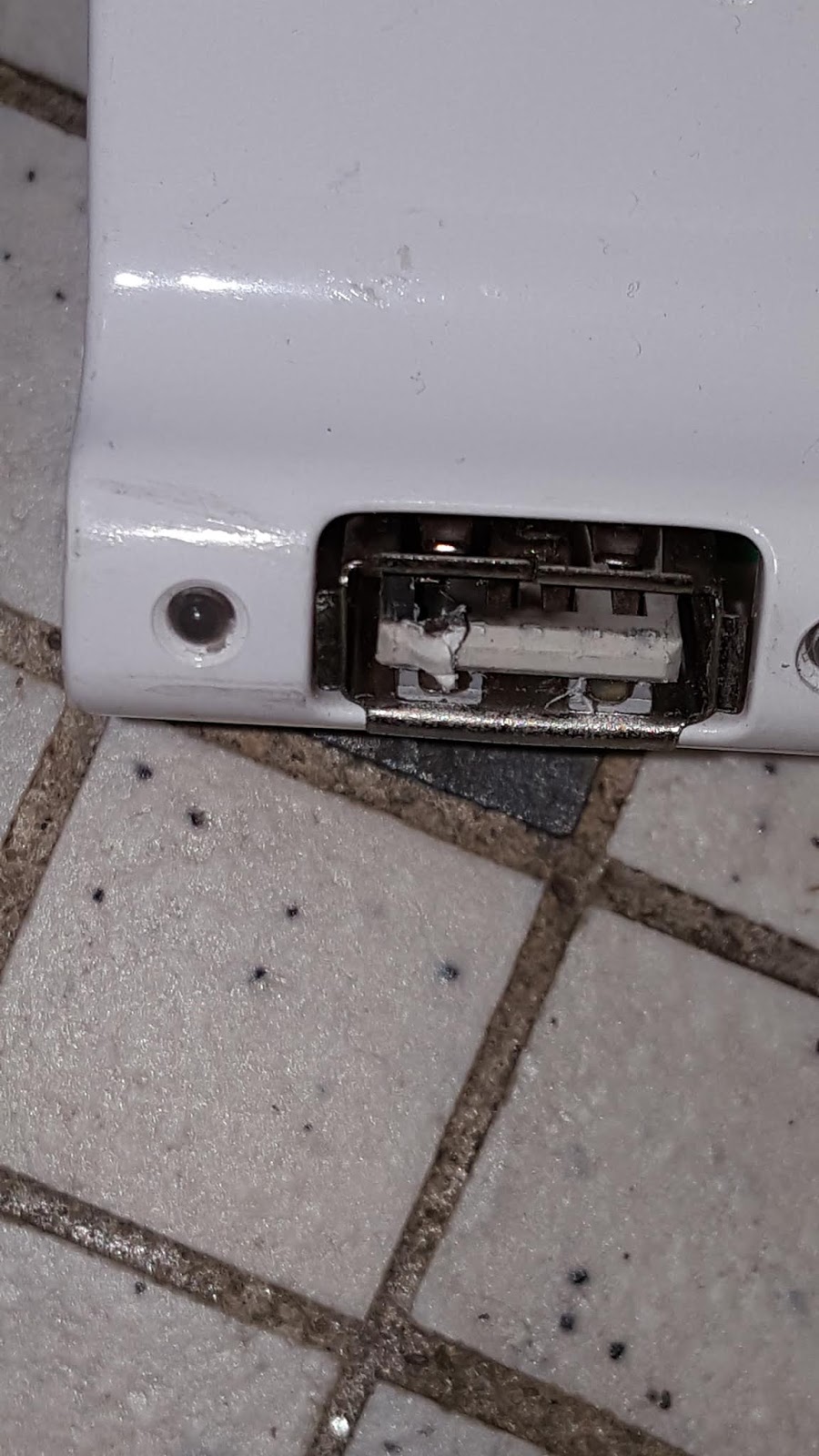
And welded the USB connector to the hub.


The USB hub socket was welded to the cable. Note the melted contact on the left.
The ESP-12E had no obvious signs of damage but was unresponsive. Happily the AS3935 was undamaged.


Burst mains 'Live' wire in the power extension cable

The 'Live' wire in the mains power extension (to laptop power adapter) open-circuited, although the 13A fuze was intact. The 3A 230V fuze in the laptop adapter blew. This calls for a rethink:
  1. the relay contacts need to be a lot better isolated from each other
  2. more isolation is needed between the relay module and the ESP-12E
  3. the power modules need to be better isolated

(Update 2020-01-22): The lightning strike propagated along the 5V rail and damaged the LM1117-3.3 regulator in the ESP-12E. It also seemed to have slightly damaged the AS3935 (which also takes 5V directly to the IC) and although its registers read normal and it can be calibrated, it no longer classified 'disturber' events as lightning, no matter how near. New parts have been ordered - this is not over!

(Update 2020-02-15): Dismantled my laptop, an Asus X751L. 


Asus X751L disassembled - one of the worst things about laptop repair is the disassembly. There are myriad flimsy plastic tabs to break and also various irreplaceable flexible cables to rip off by accident
As suspected, the fuses had blown:


Blown fuses, middle, just beside the 6-pin 19V power adapter connector. The power MOS QM3024M3 are the square 8-pin IC just to the left
The fuses lead to the drain of a QM3024M power MOSFET rated at 30V and a stonking 46A. The source is connected to a second QM3024M3, and this second MOSFET has a short-circuit from drain to source. Ouch.

The first MOSFET is likely used to turn on 19V from power adapter to the mainboard power supply unit, and the other MOSFET to connect the battery when there is no mains supply. The short-circuit means that the lightning strike short-circuited the 19V adapter output and battery output simultaneously to 0V. Indeed the battery was completely drained. Looks like I have a dead power MOSFET as well. 

Dead bug: QM3024M3 upside down. On removal the mainboard is no longer shorted


I confirmed this by de-soldering it from the mainboard.

Watch this space. Happy Trails.

"... I will do my endeavor. I try all things; I achieve what I can" - Ishmael,  'Moby Dick' by Herman Melville