Showing posts with label MQTT. Show all posts

Saturday, 26 September 2020

AS3935: The Next Generation Episode 3


"The drama's done. Why then here does any one step forth? — Because one did survive the wreck" - Herman Melville, 'Moby Dick'

It's been a strange dry season - there wasn't one. Instead of the choking haze from the fires of Indonesia, August and September brought only rain and thunderstorms. The AS3935 survived them all, until now. As usual the AS3935 detector flagged the oncoming storm. Since the lightning appears to come from the phone copper lines, esp8266 relay modules were used to disconnect the phone line from the ADSL modem. The modem is powered from a float-charged NS60 12V automotive battery. The battery charger, too was disconnected from the mains, both Live and Neutral, so as to deny the strike a path to Earth.

In order to reconnect after the storm an esp8266 4-channel module itself is powered from the same battery, but a separate 2-channel esp8266 relay module is used to disconnect the ADSL phone lines. The ADSL relay module itself is also disconnected from its 5V power supply, as previous strikes tended to jump from the relay contacts to the 5V/GND lines powering the relay coils.

The esp8266 and as3935 modules are wirelessly linked via MQTT server. 


On Thursday Sep 24, a nearby strike came in via the ADSL line, and flashed over the open relay contacts. This destroyed the 2-channel relay module (including the attached esp8266) and propagated along the 5V power line over to the 4-channel relay contacts. There it flashed over the open relay contacts to the 12V-5V buck converter and damaged it. This resulted in a short-circuit across the 12V battery and also damaged the 13.8V CC CV module used to float-charge the battery. There is no direct connection to Live, Neutral or Earth (the 4-channel relays were off).

The 4-channel relay is the only component along the strike path which survived.

From right: lightning strike along the ADSL line flashed over the relay contacts to the 5V power lines. Insulating tape was used to reduce severity of flashover


Note the burn mark along the 5V power PCB trace 


Burned area: relay coil 5V pin near relay contact connected the surge to the 5V power system and spread via the LM1117 to the ESP8266 via the 3.3V output. It also propagated to the  12V-5V buck converter

12V-5V buck converter had shorted output schottky diode SS34

13.8V CC CV float charge module takes unregulated 18Vdc and puts out 13V8 constant current constant voltage. Its output schottky diode SS54 was shorted, effectively shorting the battery

Sole survivor: 4-channel relay module used to disconnect power to battery charger and to ADSL relay module


The lightning strike must have been really close because it also took out my autogate controller and damaged lights a few houses down the street. Unlike Captain Ahab, this is where I concede defeat. After 25 years, the lightning won and I disconnected the ADSL system. 

Henceforth the future is fiber-optic. In fact it was operating concurrently with the ADSL modem when the lightning struck and it survived unscathed. At least I had Netflix.

Happy Trails.


"And I only am escaped alone to tell thee." -- Job

Sunday, 19 April 2020

AS3935 Lightning Detector: The Next Generation

“Data: My positronic brain has several layers of shielding to protect me from power surges. It would be possible for you to remove my cranial unit and take it with you.

Riker: Let me get this straight--you want me to take off your head?

Data: Yes sir”

(2020-07-19 update: see also this blog post)
Now that all my new parts have arrived, the mantra with this next iteration is isolation. The first system came to a dramatic end at the very beginning of the monsoon season. Repeated lightning strikes in the space of just a few minutes damaged every single part of the last AS3935 lightning detector. The surge nearly always ran along the phone line running into my ADSL modem.

Next Generation System is all about MQTT


First we isolate the electronics in the direct line of fire: the relay module which disconnects the ADSL line from the modem. One encouraging result is my ADSL modem survived unscathed, which is the main aim of the AS3935. The lightning surge arrived at relay COM pin and flashed over to the 5Vdc line.

ADSL Switch. Note the TTL serial lines running to the charger relay board. Hopefully the electricians' tape wrapped over the PCB traces and the relay terminals  will help resist flashovers 

And if that should come up short, we separate the relay board from the AS3935 NodeMCU ESP-12E system. Henceforth they communicate over WiFi via an MQTT server.

And where it used to share the same 5V supply as the relay board, we will now run from its own; where previously it shared the AS3935's. This still means they still share the same mains 230Vac line. And since the lightning strikes coming along the ADSL line seeks out the AC mains Live or Neutral lines, we isolate that as well: the relay 5V supply shall be derived from a 12V lead-acid battery.


From left: N40 lead-acid battery, battery charger. The white mains power cord of the charger is switched by another 2-channel relay module. Note the original charger display has been replaced by a 13.8V CV-CC DC boost-buck module
AS3935 with NodeMCU ESP-12E ESP8266 board. Note the 5V power cable is filtered by a few loops round a ferrite doughnut

The battery needs to be float-charged from a mains charger, and as an extra precaution the charger will be disconnected from the mains using a separate relay module, again cued from the MQTT server. The server will need to be run from UPS as well.

Charger mains supply cutoff relay. Note the TTL serial link from the ADSL relay module.


The AS3935 system now only publishes to the MQTT server. It is powered directly from the mains; it normally detects the storm well beforehand, and if the stroke should take out the AC mains, it does not matter for its job is done. On restoration of power it gets the last state again from the MQTT server and resumes operation.

And for debugging instead of risking a laptop running Arduino IDE, debug messages are published to the same MQTT server. More details on setting up MQTT Server in Slackware here.

The MQTT server, ADSL modem as well as the Huawei 3G Failover router all run from a UPS so on detecting an imminent a lightning strike, the ADSL line is disconnected, and IoT remote services will get maybe 2 minutes interruption  while the Huawei router switches to 3G.

As usual, the source code is in my github repository. The esp8266 code will look for an MQTT server at mqttserver.local on mDNS. Once located, they will subscribe to the topic lightning/commands and publish on lightning/messages.

An unexpected advantage is the AS3935 sensor can now be put in an electrically quieter part of the house. It seemed happiest at the back porch window, equidistant from the computers in the study and the power inverter of the refrigerator. This allowed me to increase the sensitivity setting.

For now it is set a little over-sensitive. A storm vertically overhead but too high up to trigger a strike to ground will still set it off. As does the little 50-cc 2-stroke engine from my brush-cutter. The occasional false ADSL disconnects did not bother us too much: the Huawei 3G failover system cuts over within 2 minutes, and even the IoT nodejs server does not drop its ngrok connection.

False alarm: a nearby internal combustion engine will trigger a stream of false alarms

The stage is set. It is now the inter-monsoon, and thunderstorms are beginning to come overhead, this time from the south-west. And with the Covid-19 lockdown we will be at home, for the next bout of fireworks. And all I need now is the Big Strike.

After more than 20 years, I feel a little for Captain Ahab, as played by the same excellent Patrick Stewart:


"... To the last, I grapple with thee; From Hell's heart, I stab at thee; For hate's sake, I spit my last breath at thee." - Herman Melville, Moby Dick


Happy Trails.


P.S.: A promising new relay PCB from LC Tech has slots cut around the COM pins.

LC Tech 4-Channel Relay Module
Note the slots cut around the relays' COM pin
In the last setup, the lightning struck relay COM pin, and flashed over to the 5V relay coil power line. Now the relay coil drives are optically isolated, which means the 3.3V power for the ESP8266 is better shielded from the relay contact pins.

Tuesday, 21 January 2020

3G Failover using the Huawei B310

Huawei B310 3G router
I first implemented a 3G failover using the TP-Link MR3420, but that had a few problems. It got a little erratic with less than 20 IoT devices connected. When in backup 3G mode the uplink often failed when run for too long and the 3G USB modem then needed to be power cycled. In a thunderstorm 3G reception often got a lot worse. But worst of all I could not alter the failover criteria.

This is because my benighted ADSL service provider Talikom Malaysia plumbed news depths in quality of service. The ADSL connection would get erratic, going on and off within a few minutes. Sometimes there would be an actual ADSL connection but it would not be able to reach the TM gateway and from there the Internet. Sometimes the link simply got slow.

This would sometimes cause the MR3420 to remain in ADSL mode and not fail over to 3G. Worse this sometimes caused it to randomly drop connections to some client WiFi devices. Power-cycling it usually helps, but the random dropouts are nevertheless annoying.

Huawei B310 with external antennae


The Huawei B310 has a simple failover criteria: it needed its WAN input cable disconnected before it goes into 3G mode. I could do that with an electromechanical relay; this allowed me to make a custom failover program to handle TM's myriad failure modes. Also the B310 has two connectors for 3G external antennae which are separately bought. And it does not disconnect clients in either 3G or ADSL mode.

The setup is much the same as before:


The Huawei B310's WAN uplink is taken from the Archer D50 via the DES-100S LAN switch. This allows me to disconnect the WAN link by turning off the DC power to the LAN switch. I do this using a Raspberry Pi Model B and a Piface hat.

Because of frequent electrical storms, the ADSL line can also be disconnected by an AS3935 lightning detector relay module.

The Raspberry Pi runs Raspbian. The Piface is controlled by the pifacedigitalio library and the failover program for now is a simple bash script. Here is a first-pass version of the failover program, it did not take more than an afternoon to code and test.

Because of the AS3935 lightning detector, the failover program subscribes to and publishes to a local MQTT server. The piface digitalio library is not one of you best supported ones, but there are a few hints if you run into trouble.

As always the choice of components is not necessarily optimal, if not downright obsolescent. Most of the time they are used simply because they are available on hand. Indeed you can probably get an all-singing all-dancing 3G failover modem router for a very reasonable price somewhere. But it goes against grain not to use working parts simply because they are a little too old.

Much better to go out with your boots on. Happy Trails.

Wednesday, 18 December 2019

AS3935 Lightning Detector: The Sequel

“Look aloft!” cried Starbuck. “The corpusants! the corpusants!"
 "The lightning flashes through my skull; mine eyeballs ache ... " - Captain Ahab

The rainy season came late and in its very first acid test, the AS3935 detected the oncoming storm and disconnected the ADSL modem in good time. However a really close strike after that took out the AS3935's relay module; the lightning must have arced over the open relay contacts into the 5V line. I had unwisely left my laptop connected to it to collect the debug messages, so the lightning took out my laptop as well as its power module, and plunging the neighborhood into darkness.

And to prove it was no fluke, repeated strikes on the now-unpowered system produced white arcs on a twitching relay board, a real sight to behold in the darkness. "The corpusants", like Starbuck said in Melville's 'Moby Dick'. This is probably very risky, so do proceed with caution if you ever have the misfortune to encounter this.


Scorch marks on the relay module

The over-current on the 5V line is such the heat lifted the copper trace right off the PCB.


The surge must have arced over to the nearby 5V pin on its way to the USB power line

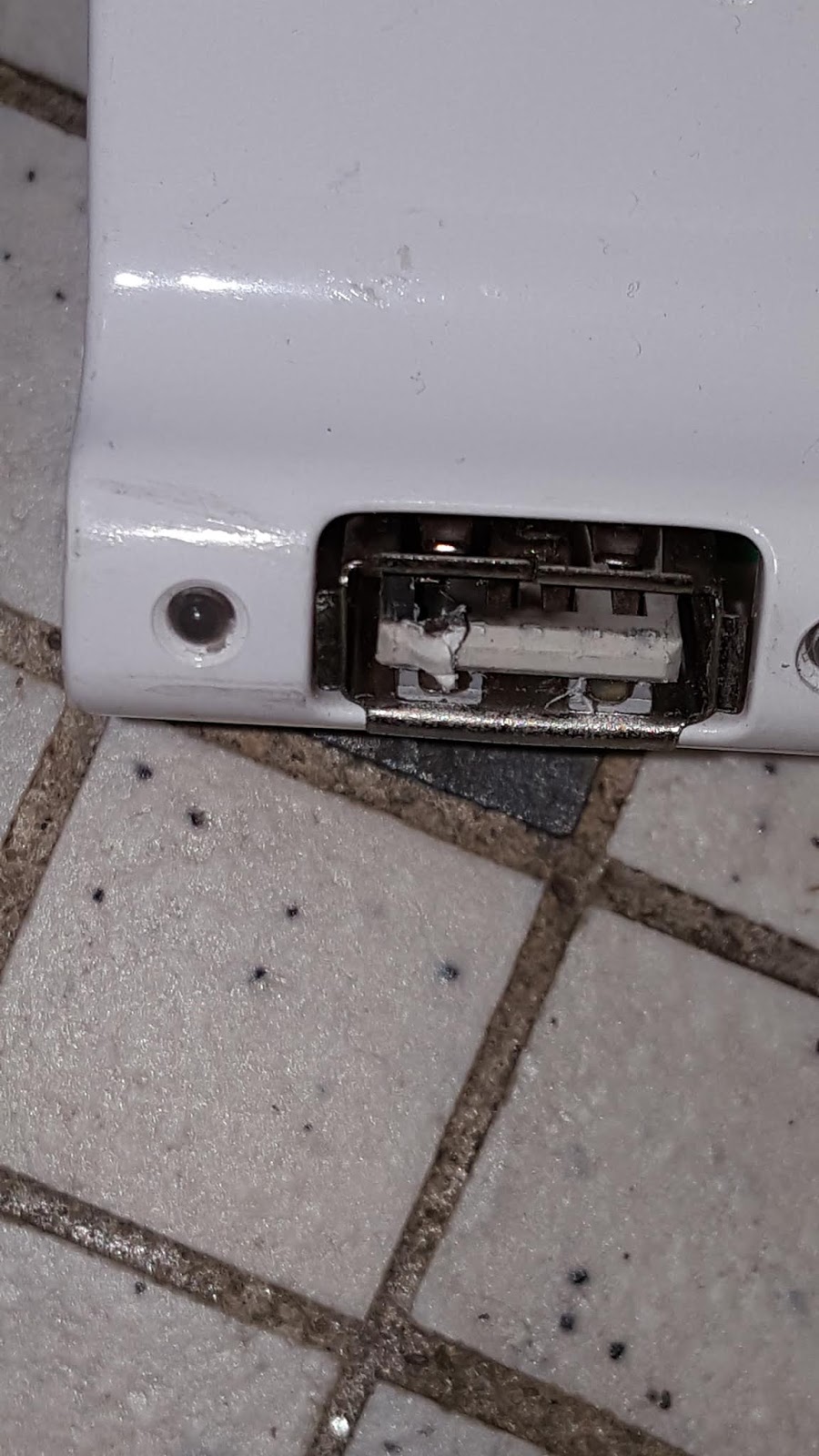
And welded the USB connector to the hub.


The USB hub socket was welded to the cable. Note the melted contact on the left.
The ESP-12E had no obvious signs of damage but was unresponsive. Happily the AS3935 was undamaged.


Burst mains 'Live' wire in the power extension cable

The 'Live' wire in the mains power extension (to laptop power adapter) open-circuited, although the 13A fuze was intact. The 3A 230V fuze in the laptop adapter blew. This calls for a rethink:
  1. the relay contacts need to be a lot better isolated from each other
  2. more isolation is needed between the relay module and the ESP-12E
  3. the power modules need to be better isolated

(Update 2020-01-22): The lightning strike propagated along the 5V rail and damaged the LM1117-3.3 regulator in the ESP-12E. It also seemed to have slightly damaged the AS3935 (which also takes 5V directly to the IC) and although its registers read normal and it can be calibrated, it no longer classified 'disturber' events as lightning, no matter how near. New parts have been ordered - this is not over!

(Update 2020-02-15): Dismantled my laptop, an Asus X751L. 


Asus X751L disassembled - one of the worst things about laptop repair is the disassembly. There are myriad flimsy plastic tabs to break and also various irreplaceable flexible cables to rip off by accident
As suspected, the fuses had blown:


Blown fuses, middle, just beside the 6-pin 19V power adapter connector. The power MOS QM3024M3 are the square 8-pin IC just to the left
The fuses lead to the drain of a QM3024M power MOSFET rated at 30V and a stonking 46A. The source is connected to a second QM3024M3, and this second MOSFET has a short-circuit from drain to source. Ouch.

The first MOSFET is likely used to turn on 19V from power adapter to the mainboard power supply unit, and the other MOSFET to connect the battery when there is no mains supply. The short-circuit means that the lightning strike short-circuited the 19V adapter output and battery output simultaneously to 0V. Indeed the battery was completely drained. Looks like I have a dead power MOSFET as well. 

Dead bug: QM3024M3 upside down. On removal the mainboard is no longer shorted


I confirmed this by de-soldering it from the mainboard.

Watch this space. Happy Trails.

"... I will do my endeavor. I try all things; I achieve what I can" - Ishmael,  'Moby Dick' by Herman Melville


Monday, 18 November 2019

Lightning detector AS3935: Part 3 of 3


Clockwise from top left: ADSL splitter, AS3935 (in vise), ESP-12E, relay module, powered USB hub, modem and POTS analog phone. All blinkenlights are go.


In the last part of this series, the AS3935 detector is hooked up to the ADSL line, and the ESP-12E is programmed to disconnect if there is a thunderstorm overhead. When the storm moves more than 8km away it will reconnect after 30 minutes.

As first mentioned in Part 2, it publishes to a local MQTT server, and also subscribes to it. This is to allow it to disconnect and reconnect the ADSL modem remotely on demand. For the last six months or so my TM Streamyx (now 'Unifi') ADSL2+ line has been unstable; dropping and reconnecting every few hours or worse. This constant failover to 3G tended to overload the TP-Link MR3420. Disconnecting the phone line during the bad periods seemed to give it some relief.

As before, the AS3935 can be quite sensitive to inteference. I ended up using separate shielded USB charger cables for 5V for both the ESP-12E and the relay module. At worst, excessive interference resulted in permanent false alarms for 'storm overhead'.

Also you can reduce false alarms by additional shielding. I partially encased the AS3935 module in a steel vise to stop it triggering when I turned on my fluorescent lights. Do not shield it completely or there will be nothing detected.

Jury-rigged steel vise shield for the AS3935


Connecting to the telephone line


My incoming POTS line has two wires, but a standard US RJ11 phone jack has at least 4. Our benighted Talikon Malaysia uses British standard (BS 6312), but most devices (not phone line) comes in the US RJ11 4-wire format, which is what I used.

Lanshack has a good page on the pinout:


The 4 wires in my RJ11 jacks cover pins 2 to 5 corresponding to Pair 1 and Pair 2. Pair 1, ie R1 & T1 at pins 3 & 4  (ie red & green wires) seem like a good starting point. I took out the modem ADSL cable, ie one with RJ11 jacks on both ends and cut it in two. The red and green cables are easily accessible.

Start with your modem phone cable, and cut in in half 


Modem cable with just Pair 1 reconnected

I verified my guess by reconnecting just Pair 1 and used my modified cable to reconnect the modem to the phone line. My ISP TM (TMnuts for short) uses ADSL2+ and that did not seem to affect my modem operation but your mileage may vary. Since broadband runs at 1Mbps up to 20Mbps changing the phone cables characteristic impedance with discontinuities like connectors and joints might affect it big-time.

Also, it would be wise to hook up the ADSL splitter and the POTS analog phone to see if they still work. If the joints did not affect your phone or modem setup, go ahead and hook up the relay module. A note of caution: disconnect the phone cable from your ISP line before you rewire. Phone line voltages are around 40Vdc and are usually safe to handle. This can change to as much as 100Vac if someone tried to call you on that phone. Be careful- phone lines can be hazardous! so you really do not want to touch the relay module when the phone is ringing.

Relay module cabling, clockwise from top left: 5V power, R1, T1 and TTL serial

I wired up the ISP side to relay Normally Open and the modem side to Relay Common. This means the relays need to be on most of the time and more power (about 100mA at 5V) will be used. The advantage is if the first strike took out the power mains, the modem will not be reconnected to the ISP.

If you only have the single relay version just switch T1 to break the circuit. This should help a lot and reduce the power of a strike, but my guess is the lightning strike can still reach the modem via R1 and if it is near enough will then complete the circuit to modem Earth or failing that to modem DC GND.

Of course if a strike is almost on top of the modem it will probably jump the relay air gaps, but the modem will be the least of your problems then. It is advisable not to go near the setup in a thunderstorm, even after the relay module has disconnected the modem. I have noticed the electronics twitching on following strikes even without power, ie after the first strike has taken out the power mains.

Software  

For esp8266 MQTT client I used pubsubclient. It was quite painless to use and its sample code worked first time with mosquitto so I will simply skip ahead to the complete version. For details on the mosquitto MQTT server, see Part 2. The nice thing about a local MQTT is that the AS3935 can then be used to disconnect more than one IoT device, for example the autogate, POTS phone extension and the satellite TV.

You can get a copy of the software from github.

To look at the MQTT output:

$mosquitto_sub -t 'AS3935/messages' -v

To turn on the relays

$mosquitto_pub -t 'AS3935/commands' -m '1'

Or you can do it from a smartphone App. I used MyMQTT. For now, you need to be in the same WiFi access point as the AS3936.

I used MyMQTT on my Android phone


As usual we keep monitoring for bugs and tuning the calibration settings. I tend to desensitize the alarms as Malaysia gets many violent but localized (ie usually not widespread) thunderstorms, and I do not want to trigger a disconnect until it is right on top of the AS3935. I also have fluorescent lights and a hot shower which tends to set it off unless I use a threshold setting of 9 and above.

This is my typical output for a real storm:

AS3935/messages 14:08:59 2019.11.19 Lightning detected 8 km away
AS3935/messages 14:09:04 2019.11.19 Lightning detected 6 km away
AS3935/messages 14:09:13 2019.11.19 Disturber detected
AS3935/messages 14:09:21 2019.11.19 Disturber detected
AS3935/messages 14:09:22 2019.11.19 Disturber detected
AS3935/messages 14:09:30 2019.11.19 Lightning detected 6 km away
AS3935/messages 14:09:45 2019.11.19 Disturber detected
AS3935/messages 14:10:07 2019.11.19 Storm overhead, watch out! Disconnecting the phone lines ..
AS3935/messages 14:20:13 2019.11.19 Disturber detected
AS3935/messages 14:31:10 2019.11.19 Lightning detected 12 km away
AS3935/messages 14:32:40 2019.11.19 Lightning detected 12 km away
AS3935/messages 14:33:18 2019.11.19 Disturber detected
AS3935/messages 14:36:02 2019.11.19 Disturber detected
AS3935/messages 14:40:08 2019.11.19 Reconnecting the phone lines ...

Once it disconnects, the software waits for the storm to move 9km away, waits a further 30min and then automatically reconnects.

At this point we just sit back and watch the light show. Happy Trails.

Wednesday, 13 November 2019

Lightning Detector AS3935: adding Serial Relay Module and MQTT Server Part 2 of 3


In Part 1, we interfaced the AS3935 lightning detector to an ESP-12E using SPI. In Part 2 here, we add an ESP-01 2-channel WiFi relay board and also set up an MQTT server.

But first, some test results. After running the system in Part 1 for a few weeks we know that:
1. There are many false (ie 'disturber') alarms
2. Some lightning strikes are incorrectly classed as 'disturber'
3. The little antenna is directional, so be careful positioning it
4. The AS3935 and relay module are best on separate 5V wires, otherwise there may be too many false alarms
5. The settings that worked for me are: Noise Floor: 3, Spike Rejection: 0, and Watchdog Threshold:2
6. There is good correlation between actual lightning strikes and the AS3935 readings
7. I have good results disconnecting the relays when the lightning is less than 5km (ie 'storm overhead') and reconnecting it 30 minutes after  lightning strikes are further than 8km away.

2-channel wifi relay module


ESP-01 2 Channel WiFi Relay Module

I got mine from lazada.com for RM27 (about USD4) each. Unlike the other ESP8266 relay boards this one has a separate CPU to activate the relays and instead of using precious GPIO pins you can do it with the serial port UART0.

makerrelay has a good writeup on a very similar module, complete with schematics and identical relay switching commands. Even better, libretto (Sergiy Zaschipas) shows you how to reprogram the relay CPU.

I can not only replace the ESP-01 with a NodeMCU ESP-12E, but I can now add relay 'channels' by simply adding more relay boards. I do not even have to use extra GPIO pins - the same TTL serial port UART0 can drive all the relay boards.

Another convenience is the relay outputs need not be reset especially since the ESP8266 is sometimes best reset if it is unable to reconnect to WiFi. If the relay CPU is reprogrammed, the ESP8266 may even read back the relay states. Since the AS3935 drops the phone line when a storm is overhead it can actually cause WiFi disconnects.

Based on some of the board markings, it is possible the original design is by LC Tech. LC Tech also provides documentation.

NodeMCU ESP-12E Pinout
You connect GP101 (also TXD0 or TX) to the pin (ESP-12E bottom right) marked 'TX' on the relay board. Connect up the adjacent GND pin to the correcponding relay module pin and you are good to go.

Relay module, solder side
Note that if you want to supply power to the relay board you need 5V which is on the other column of pins (VIN) of the ESP-12E, and not the very tempting 3.3V pin.

The relay commands are:

//Hex command to send to serial for close relay
byte relON[]  = {0xA0, 0x01, 0x01, 0xA2};
//Hex command to send to serial for open relay
byte relOFF[] = {0xA0, 0x01, 0x00, 0xA1};
//Hex command to send to serial for close relay
byte rel2ON[]  = {0xA0, 0x02, 0x01, 0xA3};
//Hex command to send to serial for open relay
byte rel2OFF[] = {0xA0, 0x02, 0x00, 0xA2};

To turn on relay 1:

Serial.write (relON, sizeof(relON));

It is that simple. My setup now looks like this:

AS3935 SPI and Relay serial port cables consolidated to one 2-headed monster. Note the 5V VIN cable on the far right. System power is via the USB cable (silver)


Top left to right: ESP-12E (partially hidden), relay module and AS3935

MQTT Server


Now that I have a way of disconnecting the ADSL modem, a convenient way to monitor the AS3935 results would be nice. Initially I simply printed the results using Serial.print() and got the output via the Arduino IDE Serial Monitor.

This worked when I am at my work station but pretty soon I was printing out to my Adafruit MQTT feed. This worked much better until a lightning storm came close enough for the relay module to disconnect the ADSL modem at which point the Adafruit connection got interrupted.

Now my WiFi does have a 3G failover, but it takes precious seconds for the Adafruit feed to re-establish itself and vital AS3935 messages are often lost. So one of the things to try would seem to be a local MQTT server, which could capture and retain my MQTT messages and if necessary upload them to my Adafruit feed for when I am offsite.

It sounds like a lot of work, until along came Mosquitto. Since my main station is still Slackware 14.2, I got my SlackBuild here:

As usual douwnload the SlackBuild tarball and unzip it:

$tar -xvpzf mosquitto.tar.gz
mosquitto/
mosquitto/slack-desc
mosquitto/README
mosquitto/mosquitto.info
mosquitto/doinst.sh
mosquitto/mosquitto.SlackBuild
usr/man/man8/mosquitto.8.gz
usr/sbin/
usr/sbin/mosquitto
usr/share/

Then download the mosquitto source code (from the SlackBuild link not the Eclipse one) and copy it into the mosquitto slackbuild directory. Then all you need is

$./mosquitto.SlackBuild

And then a Slackware install:

$upgradepkg --install-new /tmp/mosquitto-1.6.7-x86_64-1_SBo.tgz

Next you need to set up a mosquitto user:
$vi /etc/mosquitto/mosquitto.conf

And add the line:
user mosquittouser

If necessary create the new user:
$adduser mosquittouser

You start the server thus:
$mosquitto -c /etc/mosquitto/mosquitto.conf
1572678454: mosquitto version 1.6.7 starting
1572678454: Config loaded from /etc/mosquitto/mosquitto.conf.
1572678454: Opening ipv4 listen socket on port 1883.
1572678454: Opening ipv6 listen socket on port 1883.

And to check use the included client subscriber:
$mosquitto_sub -t 'test/topic' -v

The publish:
$mosquitto_pub -t 'test/topic' -m 'hello world of mosquitto'

And that was all you need. I suspect it is even easier in Debian/Ubuntu. The next thing I need would be an MQTT client for the ESP-12E, but that is another story.

So till then, Happy Trails.
Saturday, 22 December 2018

Autogate Adventures: Voice Control via Google Home. Part 3 of 3: Debugging Adafruit MQTT disconnects

One reason why I love doing software is the instant gratification: the speed at which you can try out something. And when a prototype works, the impulse is to immediately move to something else.

But a prototype is seldom suitable for customer use, and there are long weeks of grinding work where you monitor for failures and fix them as they appear.  A robust system is usually achieved sometimes years of constant fixing. If you are lucky enough to have a customer for your prototype the key is responsiveness- you need to fix it as fast as possible.

In Part 2, the MQTT-based ESP8266 IoT autogate was usable in less than a day. But it would not respond after a few days, usually after I disconnected the ADSL modem during thunderstorms (we get really spectacular lightning strikes and the ADSL modem is usually the first to go).

I can get the IoT Autogate to work again by power-cycling it, but it really looked bad next to the Sonoff switches, which seemed to recover after no more than 30 minutes as long as the broadband connection is restored. Since the Sonoff is also based on the ESP8266 and they both used the same ADSL modem and routers the problem must be the software.

Debug setup: ESP-01S on its CH340 USB Adapter


To debug the software, it would be nice to get to the Arduino IDE Serial Monitor, but since the  MQTT-based ESP8266 IoT autogate is out of reach inside the autogate enclosure. One way is to program another ESP-01S and run it on its CH340 USB adapter. When Google Assistant triggers the autogate (via IFTTT and Adafruit MQTT) both devices will now respond.

You will get messages like these every 5 seconds (Wife being the other House Member):

Wife Connecting to MQTT... Wife MQTT Connected!
Connecting to MQTT... MQTT Connected!
Wife Connecting to MQTT... Wife MQTT Connected!
Connecting to MQTT... MQTT Connected!

It would be nice to monitor it while at work, and since Adafruit's MQTT broker allows an IoT device to send messages to a feed, and since I have to make an IoT report it state back to Google Home at some point, I might as well use it to report debug messages.

In Adafruit-speak, when we want Google Assistant to control a device the ESP8266 IoT program (ie its Arduino sketch) needs to 'subscribe' to a feed. When it is sending data back to Google Assistant, it needs to 'publish'. So publish we shall. I added another feed, 'log' to my Adafruit account. 

Adafruit_MQTT_Publish mqtt_log = Adafruit_MQTT_Publish(&mqtt, AIO_USERNAME"/feeds/log");

No setup() code is necessary and you simple insert the following code snippet in loop():


{
    char logmsg[50]; 

          sprintf(logmsg, "YOUR_LOG_MESSAGE %d", Your_Log_Number); 
          if (! mqtt_log.publish(logmsg)) {
            Serial.println(F("publish Failed"));
          } else {
            Serial.println(F("publish OK!"));
          } 
}

Now log into your Adafruit account, navigate to

https://io.adafruit.com/youraccountname/feeds/log

And you have a remote Serial Monitor. It is that simple.

Logging debug messages in the Adafruit feed


But what of the ESP8266 MQTT IoT device going unresponsive problem? It turned out that just having the ESP8266 publish regularly (preferably not less than once every five minutes) made the problem go away. 

For now I can only guess when a device goes silently unresponsive, the MQTT broker may sometimes be unaware that the connection is broken, ie the mqtt.connect() function returned 0 (meaning connected) even when it is not. On the other hand we know when a periodic MQTT report does not arrive on schedule.

Notice I have disabled the "watchdog reset" to make the IoT keep trying to connect without restarting the WiFi code.    

void loop() {
  MQTT_connect();

    .
    .
    .
 publish++; 

  if (publish >= 20) //  ping every 4min
  {
    // Now we publish stuff! ping limit is 300s so 60s seems plenty
    Serial.print(F("\nPinging adafruit mqtt ... State "));
    Serial.print(State);
    Serial.print("...");
    sprintf(logmsg, "State is %d %d", State, Wife_Autogate_State);
    if (! mqtt_log.publish(logmsg)) {
      Serial.println(F("publish Failed"));
    } else {
      Serial.println(F("publish OK!"));
    }
    publish = 0;
  }
}

void MQTT_connect() {
  int8_t ret;

  // Stop if already connected.
  if (mqtt.connected()) {
    return;
  }
  
  Serial.print("Connecting to MQTT... ");
  
  uint8_t retries = 3;
  
  while ((ret = mqtt.connect()) != 0) { // connect will return 0 for connected
    Serial.println(mqtt.connectErrorString(ret));
    Serial.println("Retrying MQTT connection in 5 seconds...");
    mqtt.disconnect();
    delay(5000);  // wait 5 seconds
    //  retries--;
    if (retries == 0) {
      // basically die and wait for WDT to reset me
      while (1);
    }
  }
  Serial.println("MQTT Connected!");
}

So, for now the ESP8266 MQTT IoT Autogate goes back for more testing. We still do not know exactly what caused the problem- it might still be there for all we know. At least it is reconnecting when the Internet comes back, just like the Sonoff devices. Dave has some good work on ESP8266 reconnection problems. There is some talk here that it may be due to problems in the Expressif SDK.

By the way if you suspect the ESP8266 Adafruit MQTT library itself, you can turn on its debug messages:
 #define MQTT_DEBUG

Happily my customer (in this case Home Member Wife) does not seem to mind. We quickly got used to the Google Home/Assistant voice control of the autogate. It is especially handy when you have your hands full driving or carrying the groceries. Now if only I can get Google Assistant to recognize the dogs' voices ...

Happy Christmas, and Happy Trails.   

Friday, 30 November 2018

Autogate Adventures: Voice Control via Google Home. Part 2 of 3: ESP8266, MQTT and IFTTT

In Part 1, the autogate became a smarthome device, controlled by voice via my Google Home speaker or Google Assistant on my phone. However every time we went out, it needed four voice commands to open and close the gate.

I can also use an ESP8266 relay board, MQTT and IFTTT like I did for my ancient lantern, but there were a couple of problems. First the MQTT code would stop working after a few days. Secondly I had not figured out how to share the device on Google Home with my wife.

Top: 230Vac to 5V@1A power supply. Bottom: ESP-01S with 1-channel relay adapter

It did not take long to find out why the program stopped running. The routine MQTT_connect() is run in a loop and normally returns non-zero for a valid connection to MQTT server. However if the connection should drop (maybe WiFi interference, power outtage affecting the router, it tries to reconnect 3 times and then goes into an infinite loop waiting for a watchdog timer.

The watchdog timer is enabled by default, and is serviced by various routines in the library, so there is really no good way to use it except as a delayed reset. There is a good article on it here.

  while ((ret = mqtt.connect()) != 0) { // connect will return 0 for connected
    Serial.println(mqtt.connectErrorString(ret));
    Serial.println("Retrying MQTT connection in 5 seconds...");
    mqtt.disconnect();
    delay(5000);  // wait 5 seconds
    retries--;
    if (retries == 0) {
      // basically die and wait for WDT to reset me
      while (1);
    }
  }

The reason for the failure seems to be mqtt.connect() or perhaps the WiFi router sometimes cannot detect there is no longer a connection. For now the best workaround seems to be to have an active MQTT input, that is to regularly 'publish' to the MQTT broker Adafruit. After a few minutes (normally less than 30) mqtt.connect() will eventually work and the device will reconnect.

Getting Google Home to share the device took a little more time. On the face of it, IFTTT allows me to share: I can publish my Applet for unlimited sharing. But that is too much sharing: letting a random user open my gate from the Internet is a not good idea.

I get my MQTT service from Adafruit, (which IFTTT needs to link the ESP8266 to Google Home) and I can share just my Adafruit feed for the autogate with my wife. Indeed she can activate the autogate from the Adafruit App, but Google Home will not link to a shared feed. Furthermore the Adafruit share turned out to be a global share as well, again an unacceptable security risk.

It turned out that if I got the wife to register with IFTTT and Adafruit, and if I duplicated the ESP8266 code using my wife's Adafruit account and secret key (AIO) the device will support both Adafruit feeds.

Adafruit_MQTT_Client mqtt(&client, AIO_SERVER, AIO_SERVERPORT, AIO_USERNAME, AIO_KEY);
Adafruit_MQTT_Client wife_mqtt(&wife_client, AIO_SERVER, AIO_SERVERPORT, AIO_WIFENAME, AIO_WIFEKEY);

// Setup feeds Adafruit_MQTT_Subscribe lantern = Adafruit_MQTT_Subscribe(&mqtt, AIO_USERNAME"/feeds/frontgate");
Adafruit_MQTT_Subscribe wife_autogate = Adafruit_MQTT_Subscribe(&wife_mqtt, AIO_WIFENAME"/feeds/frontgate");

Converting the Open/Close Google Home commands to autogate pulses is now easy:

while ((subscription = mqtt.readSubscription(2000))) {
    if (subscription == &gate) {
      Serial.print(F("Got: "));
      Serial.println((char *)gate.lastread);
      int gate_State = atoi((char *)gate.lastread);
      Serial.print("Autogate openclose ");
      Serial.println(gate_State);
      digitalWrite(0, 1); // Issue a command to toggle gate
      delay(500);
      digitalWrite(0, 0); // Autogate CPU input is monostable. Issue command to reset  
    }
  }

Tight fit: clockwise from top left: autogate control board, RF remote control module, 12V battery and ESP8266 relay module

Here's a little youtube video of the result.

I am still a little unhappy with it: I would it like to feedback (ie 'publish' in MQTT-speak) actual gate open/close state, and I would have to manually dismantle and reprogram it should my parents come to visit. Also it would be nice to keep a log of the autogate usage, but perhaps that is a future project, an MQTT server. But in the spirit of DevOps, let's just put it up and look for those all-important gotchas that are so critical to a product's eventual success.

There you have it- a voice-controlled autogate. I have not looked very hard, but with a little luck, this should be one of the first homebrew Google Home autogate smart remotes.

Happy Trails.