Friday, 8 May 2020

Hacking the Raspberry Pi Model B to use with Geekworm UPS Hat


Raspberry Pi Model B (not Plus) with Composite Video socket dismounted
I recently bought a Geekworm UPS Hat for the Raspberry Pi Models B Plus and later. It has, shall we say a few rough edges. Especially running loads of 500mA and above. It often functions as a UPS at loads of say 480mA. If I paired it with a say, Raspberry Pi Model B, it works quite well.

Now I have always wanted a solar-powered wifi repeater. In the day, a solar panel provides DC power and also charges up an NS60 (nominal 60Ah at 12v) car battery. At night it runs off the battery. It seems reasonable enough: the Raspberry Pi 3 Model B Plus wifi repeater took up more than 500mA at 5V 24 hours a day, whilst the solar panel might supply 2A at 19V for maybe 6 hours a day.

But before I could buy the NS60, the Covid-19 pandemic of 2019 intervened. Rather than wait for lockdown to pass, why not reconfigure it to run from solar power in the day, and seamlessly switch over to mains power at night. I would need a couple of relays: one each for mains and solar power 5V DC-DC buck converters. And to ensure a trouble-free switchover, a UPS Hat for the Raspberry Pi would be nice ...

The Geekworm UPS Hat worked well at 500mA, and misbehaved over 600mA: the WiFi Repeater would reset on switchover. Or it would not charge the lithium battery on switching back to mains power. Now this is actually self-recovering: on the battery running down it would reset the load and the battery would charge again. There might be a minute of WiFi repeater service interruption. TM Net my service provider certainly does that a few times a day. But this is humiliating; not tolerable for anyone other than TM Net.

My Raspberry Pi Model B Plus drew 510mA clean and 600mA once the WiFi dongle started firing up. On the other hand a Raspberry Pi Model B drew only  440mA and might just work. The trouble is, the Geekworm UPS Hat has a 40-pin socket and the Model B only has a 26-pin header.

Raspberry Pi Model B's 26-pin Header

Many hardware designers seek backward-compatibility when upgrading their designs. Often old hats will work on new models, but new hats will not. But this means the headers will have a lot of similarity. Sometimes enough to work. A quick comparison shows that the first 26 pins of the 50-pin header is pretty much identical, except for GPIO 19-21. The I2C pins are the same, and crucially, so are the power and ground pins.

Raspberry Pi Model B Plus' 40-pin Header
And as long as the 3 contentious GPIO pins are not used, they will default to GPIO input, and inputs when mis-wired and unused are harmless.

But there is another problem: the Model B's composite video output, an RCA socket is too tall and gets in the way of the Geekworm 40-pin socket. This is easily de-soldered.

Remember, an electronic engineer's favorite programming language is solder!
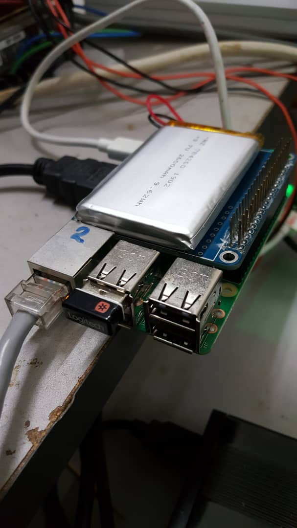
Once the RCA socket is removed, the Geekworm UPS Hat mounts nicely onto a Model B.

Geekworm UPS Hat on Raspberry Pi Model B
The Model B powers on nicely from battery. But the proof of the pudding is in the eating. Besides the Geekworm UPS I2C device at address 0x48 I also had an ADS1115 4-channel analog input card at address 0x36.

# i2cdetect -y 1
     0  1  2  3  4  5  6  7  8  9  a  b  c  d  e  f
00:          -- -- -- -- -- -- -- -- -- -- -- -- -- 
10: -- -- -- -- -- -- -- -- -- -- -- -- -- -- -- -- 
20: -- -- -- -- -- -- -- -- -- -- -- -- -- -- -- -- 
30: -- -- -- -- -- -- 36 -- -- -- -- -- -- -- -- -- 
40: -- -- -- -- -- -- -- -- 48 -- -- -- -- -- -- -- 
50: -- -- -- -- -- -- -- -- -- -- -- -- -- -- -- -- 
60: -- -- -- -- -- -- -- -- -- -- -- -- -- -- -- -- 
70: -- -- -- -- -- -- -- --             

And from my last post

# ./ups_read
97

# ./ups_read -vc
4.161250V 96.550781%


Blinkenlights galore: Raspberry Pi Model B booting from battery power

To probe it a little further, I printed out a few more registers of the MAX17048:
# ./ups_read2 -a
MODE 10 00
CFG 97 1c
CRATE ff f9
VER 00 12
STAT 00 ff
VRST 00 0c
VCELL cf f0
CREG 60 65
4.158750V 96.394531%

The code is in my github repository.

Note that the 5V input into the Geekworm UPS Hat greatly affects its operation. In the picture of the WiFi extender below, a smaller 5V DC-DC buck converter (red PCB) was used, and this resulted in the Geekworm Hat not charging. Swapping it out for a 5V 3A unit (blue PCB) did the trick. Note that when the battery is at full charge, it takes a little while, maybe a few minutes, for the Hat to start charging.

Raspberry Pi Model B with Geekworm UPS Hat, installed as daytime solar powered WiFi extender . From top: ADS1115 I2C analog converter, WiFi dongle, Pi Model B with Geekworm UPS Hat, 2A buck converter(disconnected), and 3A CC CV buck converter

And yes, the Raspberry Pi daytime solar WiFi Repeater works for now. It's early days yet and there are many switchovers and switchbacks yet to come.

And there you have it: how to hack a 26-pin Raspberry Pi Model B for the Geekworm UPS Hat.

Happy Trails


Thursday, 30 April 2020

Geekworm Raspberry Pi UPS Hat

I did not really have much faith in the Geekworm Raspberry Pi UPS Hat. It cost just RM48 and change and it came with a 3.7V 2700mAh lithium battery. The software links did not work (the correct link is here) and the driver looked out of date.

Plus there has been some rather harsh comments about it. Some like this one, seems reasonable. Now I am not saying they are wrong, but that Geekworm Raspberry Pi UPS Hat worked for me, much to my surprise.

It is quite well described here and I will not repeat the information. I originally had the idea of using a store-bought power bank for the very same purpose. I thought if I ran the power bank with the charger always connected and the raspberry Pi always drawing power, it should work like a cheap UPS. Not bad for an RM30 no-name 3000mAh power bank.
Power bank as UPS. Note the Qi receiver coil
I found one while walking my dogs. It's cover was cracked open and it looked like it had been thrown out of a car, but when it was dried out it worked. The battery looked intact, did not overheat and was not bulging.

But sadly it did not work consistently. When the mains charger was powered off it ran from battery well enough. The problem was when the charger was switched on, it sometimes rebooted. Looks like the output power was not quite stable enough during the switchover. A common enough problem with regular UPS.

Now I can still use it as a UPS for systems that can tolerate a reboot. In some cases I simply put a little restart code in /etc/rc.local. And I can't really complain about the price. Do be careful of discarded lithium batteries though. They have been known to explode, or burn white-hot.

But a real UPS would switch over and back without a glitch. And it would be nice to have an indication of the battery state. The Geekworm UPS actually looked like (I am not sure; I did not check) it was adapted from a power bank circuit  and it would be good so see where I fell short.

Having heard some comments about bad batteries, miswired batteries and faulty UPS boards, I checked both the battery output and the polarity before I hooked it up. It all checked out and powered on a Raspberry Pi 3 Model B+ quite nicely while still on charge.

Geekworm UPS Hat installed
It ran nicely on battery, and did not reset when the charger is reconnected. Even when running X Windows, Chrome and a youtube video at 1900x1080 resolution.

The extremely brief 'manual' (http://raspberrypiwiki.com/File:UserManual.pdf) called for installation of a driver:

User Guide:
1. Upgrade software:
sudo apt-get update
sudo apt-get upgrade
2. Enable the I2C function via raspi-config tool.
3. Install wiringPi .
git clone git://git.drogon.net/wiringPi
cd wiringPi
git pull origin
cd wiringPi
./build
4. Download the zip package;?rpi-ups-hat.zip?
unzip rpi-ups-hat.zip
cd rpi-ups-hat
5. Run the tested program
sudo python example.py

But there is also a C program, which I reproduce in full here:
$cat main.c

#include <unistd.h>                     // close read write
#include <stdio.h>                      // printf
#include <fcntl.h>                      // open
#include <linux/i2c-dev.h>
#include <sys/ioctl.h>
#include <getopt.h>


#define VREG 2
#define CREG 4
#define BUFSIZE 16
#define DEV "/dev/i2c-1"
#define ADRS 0x36


static int readReg(int busfd, __uint16_t reg, unsigned char *buf, int bufsize)
{
    unsigned char reg_buf[2];

    reg_buf[0] = (reg >> 0) & 0xFF;
    reg_buf[1] = (reg >> 8) & 0xFF;

    int ret = write(busfd, reg_buf, 2);

    if (ret < 0) {
        printf("Write failed trying to read reg: %04x (0x%02x 0x%02x)\n", reg, r
eg_buf[0], reg_buf[1], reg);
        return ret;
    }

    return read(busfd, buf, bufsize);
}

int main(int argc, char **argv)
{
    int vOpt = 0, cOpt = 0, o;

    while ((o = getopt (argc, argv, "vc")) != -1) {
        switch (o)
        {
        case 'v':
            vOpt = 1;
            break;
        case 'c':
            cOpt = 1;
            break;


        }
    }

    int bus = 1;
    unsigned char buf[BUFSIZE] = {0};

    int busfd;
    if ((busfd = open(DEV, O_RDWR)) < 0) {
        printf("can't open %s (running as root?)\n",DEV);
        return(-1);
    }

    int ret = ioctl(busfd, I2C_SLAVE, ADRS);
    if (ret < 0)
        printf("i2c device initialisation failed\n");

    if (ret < 0) return(-1);

    readReg(busfd, VREG, buf, 2);

    int hi,lo;
    hi = buf[0];
    lo = buf[1];
    int v = (hi << 8)+lo;
    if (vOpt) {
                printf("%fV ",(((float)v)* 78.125 / 1000000.0));
        }

    readReg(busfd, CREG, buf, 2);
    hi = buf[0];
    lo = buf[1];
    v = (hi << 8)+lo;
    if (!cOpt && !vOpt) {
                printf("%i",(int)(((float)v) / 256.0));
        }
        if (cOpt) {
                printf("%f%%",(((float)v) / 256.0));
        }

        printf("\n");

    close(busfd);
    return 0;

}

I started with the usual:

sudo apt-get update
sudo apt-get upgrade

And used raspi-config to turn on i2c. As soon as I did that an i2c device came up:

# ls -l /dev/i2*
crw-rw---- 1 root i2c 89, 1 Apr 30 20:28 /dev/i2c-1

A quick scan of the C program main.c showed that that was all it needed to run. So, I skipped all the other steps and went straight to:

# gcc main.c -o ups_read

And it runs:
# ./ups_read
97

When I disconnected the charger and ran on battery it actually reads a little higher:
# ./ups_read
98

But it quickly starts to show a correct, discharging trend:
# ./ups_read
97

I ran it for some 6 minutes at pretty much full power and it went to 83%:
# date;./ups_read
Thu Apr 30 20:46:49 +08 2020
83

When I plugged the charger in I get the wobble:
# date;./ups_read
Thu Apr 30 20:47:27 +08 2020
82
            And yes, it charges:
# date;./ups_read
Thu Apr 30 20:47:49 +08 2020
83

# ./ups_read -vc
4.161250V 96.550781%

And that was all it took. Raspberry Pi UPS Hat on the cheap.

Happy Trails.


[Update 2020-05-06]
Managed to reproduce some of the problems mentioned above by increasing the current drawn from the UPS. Decreasing the UPS input power did not affect it much, except it increased the charging time. But, if I increased the UPS load too much (by loading up the Pi USB ports with for example a WiFi dongle at full power), a switchover from mains to battery supply now caused the Pi 1 to reset. And on reboot, the Geekworm UPS often failed to charge unless the load is power-cycled.

600mA peak current draw from the Geekworm UPS Hat was enough to trigger the problems mentioned. A 510mA peak draw was more or less OK for trouble-free operation. Treat the numbers as a guide: I only used a USB Charge Doctor to measure the peak current consumption. This almost guarantees an incorrect reading. An oscilloscope would be a better choice.  

The 4 LED do not accurately reflect the battery state of charge. The I2C value read by ups_read is much more accurate.  

Sunday, 19 April 2020

AS3935 Lightning Detector: The Next Generation

“Data: My positronic brain has several layers of shielding to protect me from power surges. It would be possible for you to remove my cranial unit and take it with you.

Riker: Let me get this straight--you want me to take off your head?

Data: Yes sir”

(2020-07-19 update: see also this blog post)
Now that all my new parts have arrived, the mantra with this next iteration is isolation. The first system came to a dramatic end at the very beginning of the monsoon season. Repeated lightning strikes in the space of just a few minutes damaged every single part of the last AS3935 lightning detector. The surge nearly always ran along the phone line running into my ADSL modem.

Next Generation System is all about MQTT


First we isolate the electronics in the direct line of fire: the relay module which disconnects the ADSL line from the modem. One encouraging result is my ADSL modem survived unscathed, which is the main aim of the AS3935. The lightning surge arrived at relay COM pin and flashed over to the 5Vdc line.

ADSL Switch. Note the TTL serial lines running to the charger relay board. Hopefully the electricians' tape wrapped over the PCB traces and the relay terminals  will help resist flashovers 

And if that should come up short, we separate the relay board from the AS3935 NodeMCU ESP-12E system. Henceforth they communicate over WiFi via an MQTT server.

And where it used to share the same 5V supply as the relay board, we will now run from its own; where previously it shared the AS3935's. This still means they still share the same mains 230Vac line. And since the lightning strikes coming along the ADSL line seeks out the AC mains Live or Neutral lines, we isolate that as well: the relay 5V supply shall be derived from a 12V lead-acid battery.


From left: N40 lead-acid battery, battery charger. The white mains power cord of the charger is switched by another 2-channel relay module. Note the original charger display has been replaced by a 13.8V CV-CC DC boost-buck module
AS3935 with NodeMCU ESP-12E ESP8266 board. Note the 5V power cable is filtered by a few loops round a ferrite doughnut

The battery needs to be float-charged from a mains charger, and as an extra precaution the charger will be disconnected from the mains using a separate relay module, again cued from the MQTT server. The server will need to be run from UPS as well.

Charger mains supply cutoff relay. Note the TTL serial link from the ADSL relay module.


The AS3935 system now only publishes to the MQTT server. It is powered directly from the mains; it normally detects the storm well beforehand, and if the stroke should take out the AC mains, it does not matter for its job is done. On restoration of power it gets the last state again from the MQTT server and resumes operation.

And for debugging instead of risking a laptop running Arduino IDE, debug messages are published to the same MQTT server. More details on setting up MQTT Server in Slackware here.

The MQTT server, ADSL modem as well as the Huawei 3G Failover router all run from a UPS so on detecting an imminent a lightning strike, the ADSL line is disconnected, and IoT remote services will get maybe 2 minutes interruption  while the Huawei router switches to 3G.

As usual, the source code is in my github repository. The esp8266 code will look for an MQTT server at mqttserver.local on mDNS. Once located, they will subscribe to the topic lightning/commands and publish on lightning/messages.

An unexpected advantage is the AS3935 sensor can now be put in an electrically quieter part of the house. It seemed happiest at the back porch window, equidistant from the computers in the study and the power inverter of the refrigerator. This allowed me to increase the sensitivity setting.

For now it is set a little over-sensitive. A storm vertically overhead but too high up to trigger a strike to ground will still set it off. As does the little 50-cc 2-stroke engine from my brush-cutter. The occasional false ADSL disconnects did not bother us too much: the Huawei 3G failover system cuts over within 2 minutes, and even the IoT nodejs server does not drop its ngrok connection.

False alarm: a nearby internal combustion engine will trigger a stream of false alarms

The stage is set. It is now the inter-monsoon, and thunderstorms are beginning to come overhead, this time from the south-west. And with the Covid-19 lockdown we will be at home, for the next bout of fireworks. And all I need now is the Big Strike.

After more than 20 years, I feel a little for Captain Ahab, as played by the same excellent Patrick Stewart:


"... To the last, I grapple with thee; From Hell's heart, I stab at thee; For hate's sake, I spit my last breath at thee." - Herman Melville, Moby Dick


Happy Trails.


P.S.: A promising new relay PCB from LC Tech has slots cut around the COM pins.

LC Tech 4-Channel Relay Module
Note the slots cut around the relays' COM pin
In the last setup, the lightning struck relay COM pin, and flashed over to the 5V relay coil power line. Now the relay coil drives are optically isolated, which means the 3.3V power for the ESP8266 is better shielded from the relay contact pins.

Thursday, 2 April 2020

Microchip ENC28J60 SPI Ethernet controller

From bottom: ENC28J60 SPI Ethernet Controller, Raspberry Pi 3 B and 5V 6A power module
The Microchip ENC28J60 Ethernet Controller has an SPI interface which makes it possible to retrofit LAN functionality to microcontroller systems, especially legacy ones. Now the ESP8266 is a much more obvious choice, but sometimes it is handy to use a wired, or copper LAN.

As is often the case it turned out it is easier to test the ENC28J60 using a Raspberry Pi. Usually because the software is easily available, but in this case because TheSpotShed has a great writeup on it. My board is a little different from his, but even so it worked first time, so for more details hie you hence to TheSpotShed.

Now a late-model Pi is far from a tiddly microcontroller, and we often forget that the Network Stack takes up more than one third of the 15-million plus lines of Linux kernel source code. It is a measure of how far we have come to even consider implementing networking in an embedded microcontroller system. Besides being a slam-dunk, implementing it for a Pi lets you gauge where the bottlenecks are: the SPI interface, the LAN controller or the microcontroller.

My ENC28J50 board had different pinout from the one in TheSpotShed, and it runs on 5V instead of 3.3V. There are a few spelling errors, e.g. LNT instead of INT, SL instead SI

I bought my ENC28J60 from lelong.com.my's enewground before it was removed from sale
Plus the pinouts were different. My cable is thus:

Pi                      ENC28J60     Colour
------------------------------------------------
+3V3                  VCC          Brown            <--- Note my PCB is *5V*
GPIO10/MOSI    SI              Grey
GPIO9/MISO     SO             Green
GPIO11/SCLK   SCK          Purple
GND                  GND          Red

GPIO25              INT           Orange
CE0#/GPIO8      CS            Black

Working from 5V also meant that my 10-way Molex header (SL Modular Connector, 70066 Series IDC/IDT 2.54mm) no longer sufficed. I had to run a couple of easyhooks to the top of the Raspberry Pi header for my 5V. Other than that, everything worked on the first try, so kudos to TheSpotShed.

First I checked for the enc28j60.dtbo overlay:

# mount /dev/mmcblk0p1 /mnt/flash
# ls -l /mnt/flash/overlays/enc*
-rwxr-xr-x 1 root root 1403 Nov 19  2018 /mnt/flash/overlays/enc28j60.dtbo
-rwxr-xr-x 1 root root 1279 Nov 19  2018 /mnt/flash/overlays/enc28j60-spi2.dtbo

It is not only there but very promisingly there looks to be provision for a second spi interface, spi2.

A quick edit of /boot/config.txt to add:
dtparam=spi=on
dtoverlay=enc28j60

And on reboot, it came up immediately as eth1:

# ifconfig -a
eth0: flags=4163<UP,BROADCAST,RUNNING,MULTICAST>  mtu 1500
        inet xx.xx.xx.xx  netmask 255.255.255.0  broadcast xx.xx.xx.255
        ether b8:27:eb:a4:ab:0b  txqueuelen 1000  (Ethernet)
        RX packets 85  bytes 9631 (9.4 KiB)
        RX errors 0  dropped 0  overruns 0  frame 0
        TX packets 68  bytes 8877 (8.6 KiB)
        TX errors 0  dropped 0 overruns 0  carrier 0  collisions 0

eth1: flags=4099<UP,BROADCAST,MULTICAST>  mtu 1500
        ether 4e:cd:f6:c2:4e:3a  txqueuelen 1000  (Ethernet)
        RX packets 0  bytes 0 (0.0 B)
        RX errors 0  dropped 0  overruns 0  frame 0
        TX packets 0  bytes 0 (0.0 B)
        TX errors 0  dropped 0 overruns 0  carrier 0  collisions 0
        device interrupt 167

lo: flags=73<UP,LOOPBACK,RUNNING>  mtu 65536
        inet 127.0.0.1  netmask 255.0.0.0
        loop  txqueuelen 1000  (Local Loopback)
        RX packets 0  bytes 0 (0.0 B)
        RX errors 0  dropped 0  overruns 0  frame 0
        TX packets 0  bytes 0 (0.0 B)
        TX errors 0  dropped 0 overruns 0  carrier 0  collisions 0
wlan0: flags=4163<UP,BROADCAST,RUNNING,MULTICAST>  mtu 1500
        inet zz.zz.zz.zz  netmask 255.255.0.0  broadcast zz.zz.255.255
        ether b8:27:eb:f1:fe:5e  txqueuelen 1000  (Ethernet)
        RX packets 22  bytes 2202 (2.1 KiB)
        RX errors 0  dropped 0  overruns 0  frame 0
        TX packets 26  bytes 3454 (3.3 KiB)
        TX errors 0  dropped 0 overruns 0  carrier 0  collisions 0

On connecting it to my modem router the link came up immediately. I tested it with Youtube with Firefox, and it pretty much ran a full HD (1080p) music video, with the odd hiccup or two. But overall very impressive throughput, compared to my previous SPI link to my SIM7000C 3G modem.

Sistar's 'Give it to Me' in fullscreen mode is a brutal workout for anything less than a Linux workstation 
The next thing to do would be to hook the ENC28J60 to an ESP8266, but that is another blog post, so watch this space.

Keep safe, and Happy Trails.

Wednesday, 4 March 2020

IoT Home Alarm: A New Beginning

Active House Alarm: Malaysian street-dogs are very territorial and alert 


Over the years I have been working on and off on my Home Alarm system, always upgrading it but never quite happy with it. I did arrive at some thoughts for a good alarm, which are:

  1. It is not always ideal to catch the intruder. In the suburbs a break-in is often done by someone familiar with the neighborhood. Often he is a neighbor, a relative/friend of a neighbor who visits or house-sits. The penalty for a first offense break-in is only a few months incarceration, and after it is over, guess what, he is still your neighbor except this time he hates you. Deterrence is a better goal for a home alarm: how to convince a prospective intruder to burgle elsewhere. Even if the system gets a positive ID on the intruder, it is often better to pop a printout of the offender into his letterbox: the prospect of jail-time is is a much better deterrence.
  2. The best deterrence is a concerned neighbor who investigates the alarm, sticks his head out the window, turn the light on, or somehow lets the intruder know the jig is up. He should not intervene or confront the bad guy, just the prospect of a call to the police is often enough. Of course, if your immediate neighbor is the bad guy then you have a big problem.
  3. It then follows that a good alarm should have minimal false alarms: you do not want to annoy your neighbor, and worse, condition him not to investigate.
  4. A successful burglary often means he will come back. He already knows the layout of the house, mode of entry, as well as the payoff.  
  5. There is no such thing as a perfect alarm system. Determined intruders will always find a way in. The key goal is to convince them to go elsewhere. Like that Asics jogging shoes ad, when confronted by a lion it is sufficient just to outrun your companion. 


Asics running shoes ad
The features of a reasonably effective home alarm should then be:
  1. Able to identify the intruder. This usually means high-resolution cameras with good lighting. It is a problem if he is masked, so they should also cover the driveway to identify the getaway vehicle. Ideally a light source just behind the camera should switch on. It is instinct to look at the light: you then get good face shots. There is nothing more annoying than camera footage which almost IDs the intruder. To minimize false alarms the camera should not trigger the siren. 
  2. Able to raise the alarm. A siren is often enough. It should not go on for more than a few minutes: few intruders will hang around that long. The ones that do: well you probably don't want your neighbor to mess with them. Sensors that trigger the siren should be door or window switches, indoor passive infrared sensor, drawer micro-switch, etc. 
  3. Notify you when offsite. This lets you review the sensors and perhaps call for help.
  4. Do unexpected things. Popular commercial alarms behave in well-known, and hence predictable ways to knowledgeable intruders. Especially the sound of a snarling dog - the prospect of immediate personal injury is quite distracting. Just make sure it is not played too long. It is best not to install booby traps (paintball gun is my favorite) - they almost always catch the house occupants at some point.  
The good news is current IoT developments bring exciting new capabilities. Even inexpensive IP cameras come with motion detection and some ability to recognize humans. This is especially useful when sifting through hours and hours of security footage. Intruders often do quick surveys from  outside; so a good deterrence is posting a printout of them doing just that. A bonus is you get confirmation of online purchased deliveries. 

Smartphone Apps now allow the alarm to contact you remotely. And best of all, wireless sensors remove a major disincentive to alarm installations: expensive and often unsightly wiring. 

Best of all the IoT parts required are cheap and getting cheaper. So it is time to make a start. And a good start is a passive infrared (PIR) sensor linked directly to a siren. This way I can incrementally add to the system without needing to take it down for upgrades.

The HC-SR501 cost me only RM5 (about USD1). Note the range and delay adjustments are especially handy
The HC-SR501 PIR sensor costs only RM5 from Cytron. The HC-SR505 on the other hand was less useful as the range is a little short and not adjustable. And the price is not much different.

HC-SR501 Schematic


You can pretty much hook up the HC-SR501 directly to a siren via a relay module

The HC-SR501 can be used to directly trigger a siren. But adding an ESP8266 will let the siren be triggered by other sensors in the future. And little conveniences like alarm arm/disable functions from the smartphone.

1-channel ESP-01S Relay Module, shown with ESP8266-based ESP-01S installed

This 1-Channel ESP8266-based ESP-01S Relay Module is slightly problematic when used with an ESP-01S (see my post on this). However it can be used unmodified with the NodeMCU ESP-12E. This relay module is not to be confused with the Diymore Serial 1-channel ESP8266 Relay Module, which has an onboard CPU and is triggered from the serial port rather than a GPIO line:

Serial TTL 1-Channel ESP8266 Relay Module, with ESP-01S mounted

I found the ESP-01S a little problematic getting the GPIO lines to work as input, so for this build I used the NodeMCU ESP-12E instead:


ESP-12E NodeMCU development board, with CH340 USB interface

Wiring Diagram
The wiring is, from the point of view of the ESP-12E:
GPIO13 - Relay control line
GPIO12 - PIR output
The assembled system looks like this:

Left to right: USB power connector, NodeMCU ESP-12E, 1-channel ESP8266 Relay Module and HC-SR501 PIR sensor
You connect your siren to the relay contacts. This lets you switch most sirens, from mains powered sirens, 12V automotive car horns or a more discreet 5V buzzer. Personally, I find the 12V automotive siren plenty loud and easy to back up with car batteries.

12V Siren


As usual there is a sample program in github.  The program creates a WiFi access point, "SirenAccessPoint". and you log into it using your smartphone. You then type into your favorite browser:
http://192.168.4.1/arm           to turn the alarm on
http://192.168.4.1/disable      to turn the alarm off
http://192.168.4.1/sirenon      to turn the siren on
http://192.168.4.1/sirenoff     to turn the siren off

As a start the system does not assume you have a WiFi infrastructure, and you can pretty much move it to any location you want to protect. One caveat is many PIR sensors are triggered by direct sunlight, so your mileage will vary.

By having other devices to log into the AP, we can now trigger, disarm or mute the siren using the same http messages. However a true IoT system needs a way to contact your smartphone offsite. For that we will be needing some kind of communications infrastructure, usually an MQTT gateway. For simplicity, later iterations of this project will use WiFi broadband, as with the other IoT projects in this blog.

There are many things to add: door magnetic switches, IP cameras, motion detectors and lighting control. But there you have it: a cheap DIY House Alarm to start you off. 

Nightwatch


In the meantime, I have a pair of rescued Malaysian street-dogs on duty round the clock, and honestly, that IoT Alarm System has a lot to live up to.

Happy trails.

Tuesday, 28 January 2020

Hacking the HW-655 ESP8266 WiFi IoT Relay Board

HW-655
I got my HW-655 for just RM10, ESP-01S included. However it did not work and I suspected the seller just plain forgot to program the STC15F104W CPU. Luckily, Sergiy Zaschipas has a great writeup on this and I strongly recommend a careful read.

[2020-07-12 update: here's the hack for the 2 relay Nuvoton N76E003 CPU version]

I had always wanted to reprogram these serial relay modules. They are perfect for use with the ESP-01S. When reprogrammed a number of them can be daisy-chained on the same serial port allowing a single ESP-01S to control them all. They can also be daisy-chained without reprogramming, but then all the relays would turn on and off at the same time.

The same serial port is brought out to a header and this also lets a Raspberry Pi control the relay daisy-chain with a minimum of wiring. The usual hat is maybe the Piface Digital or Piface Digital 2, but of late Piface libraries has been buggy and it has begun to feel like abandonware.

So hie you hence to Zaschipas' repository. There stays a program to make you a working HW-655. Since I mostly run Slackware, I would add a few notes. sdcc, the compiler for the 8051 CPU (STC15 is an Intel 8051 derivative) is installed thus:

$tar -xvjf sdcc-src-3.9.0.tar.bz2

But you will first need gputils:
gputils-1.5.0$./configure
gputils-1.5.0$make clean
gputils-1.5.0$su -c "make install"

Then to sdcc proper:
sdcc-3.9.0$./configure

The compile takes a long time so if you have the resources to run it in parallel, I would recommend:

sdcc-3.9.0$make -j 10
sdcc-3.9.0$su -c "make install"

If you do not want to compile Sergiy's relay.c from source, here are my results:
$cat relay.ihx
:0400000002001132B7
:03000B0002012CC3
:03006A0002000E83
:03000E0002006D80
:20006D0075415575425075B10075B204C2B2753B00753D00C20412019BE4F53FF540E53F55
:20008D002441F9E7FF600F8F8212018F053FE4B53FEC054080E810030302011985223CE53E
:2000AD003B24FC5003020119E53B75F003A49000BF730200CB0200D40200E20200F974A0E5
:2000CD00B53C49053B80457401B53C04053B803C753B0080377401B53C028004E53C700783
:2000ED00053B853C3D8025753B00802074A2B53C0B7401B53D06D2B2D204800D74A1B53C54
:20010D0008E53D7004C2B2D204753B001004030200A3A2B2E433F58212018F0200A322C073
:20012D00E0C0D0300120D52628752603D52809852422C201D2038019E524C313F52430B056
:20014D0010432480800B20B008D201752604752809D52529752503300023E527700AC2B114
:20016D008521237527098015E523C313F523D52708D2B1C200D2028004A2D792B1D0D0D0AC
:20018D00E032AF8210020280FB8F21D20022759850C2AFC2B9C2A9C28C758900758E8075E4
:1C01AD008A80758CFED28CD2A9D2B9D2AFC200C201D202C20375250075260022D3
:06004000E4787FF6D8FD14
:20001E007900E94400601B7A009001CD780175A000E493F2A308B8000205A0D9F4DAF275BA
:02003E00A0FF21
:200046007800E84400600A790175A000E4F309D8FC7800E84400600C7900900001E4F0A3B8
:04006600D8FCD9FAEF
:0D0011007581421201C9E582600302000EF4
:0401C9007582002219
:00000001FF

The utility to program the STC15 is stcgal and I installed it thus:

$pip3 install stcgal

Getting stcgal to program was very tricky. I used a CH340 USB to serial ttl dongle set for 3.3V.

CH340

What worked for me was to run the CH340 and the HW-655 from separate 5V power supplies, the latter seemed to work better from  battery-power, like from a power bank. Unusually, I had to connect the CH340 TX to HW-655 TX and RX to RX (you usually connect TX to RX), but your mileage may vary. You then ran the programming command; mine is slightly different from Sergiy's:

Programming setup: CH340 in center and the 1-channel serial relay module on top. Wires are TX-TX, RX-RX and GND-GND


$stcgal -p /dev/ttyUSB0  -b 1200  -D relay.ihx

To test, the python interpreter makes it fun and easy:
$python                     
Python 2.7.16 (default, Apr  3 2019, 21:30:55)
[GCC 8.3.0] on linux2
Type "help", "copyright", "credits" or "license" for more information.
>>> import serial
>>> port = serial.Serial("/dev/ttyUSB0", baudrate=9600, timeout=3.0)         
>>> relON = [0xA0,0x01,0x01,0xA2]
>>> port.write(serial.to_bytes(relON))
4

To use it with the ESP-01S, I need an Arduino IDE sketch. And it worked first time, just like that. The baudrate is 9600. The code repository is in github. To turn on the relay you use a browser with the URL:
http://ww.xx.yy.zz:8080/1/on

You can pick up the device IP address from your router but I used the 'Tools->Port' sub-menu in Arduino IDE which lists the device IP address.

In my installation, the ESP-01S often had to be reset when it has WiFi disconnects and when you use it to control relays this annoyingly resets the relay as well. I can probably flash the relay state into ESP8266 filesystem, but this tends to wear out the flash memory. But the great thing with having a separate CPU like the STC15 is that the relay state is still preserved in there. Except now you need a command to read the relay state back.

First we need to decode the relay commands used. They are:

0xA0, 0x01, 0x01, 0xA2 to turn on a relay
0xA0, 0x01, 0x00, 0xA1 to turn off a relay

Notice the STC15 replies with a 1-byte reply with the actual state of the relay control line.
For modules with two relays the commands for the second relay are:

0xA0, 0x02, 0x01, 0xA3
0xA0, 0x02, 0x00, 0xA2

My guess would be the first byte A0 is the header to indicate the start of a command packet. Next byte would be the relay number, and the third byte would be relay operation code, ie 0 for off and 1 for on. The last byte would be a checksum, which is just a straight sum of the preceding 3 bytes.

So for my relay daisy chain, I would extend the commands as follows for relay 3:

0xA0, 0x03, 0x01, 0xA4 to turn on relay 3
0xA0, 0x03, 0x00, 0xA3 to turn off relay 3

And so on. Now for the relay state read I would propose a new opcode 2, so to read relay 1:

0xA0, 0x01, 0x02, 0xA3

And the answer would be in the same 1-byte reply. I implemented this in the relay_read.c program. To read the state from the ESP-01S I would use a browser and the URL:
http://ww.xx.yy.zz:8080/1/read

For installations were hazardous voltages in the relay module need to be completely enclosed, an external ESP8266 with TTL Serial Adapter PCB may improve WiFi reception


There you have it, an HW-655 in the palm of your hand. Happy trails.

Tuesday, 21 January 2020

3G Failover using the Huawei B310

Huawei B310 3G router
I first implemented a 3G failover using the TP-Link MR3420, but that had a few problems. It got a little erratic with less than 20 IoT devices connected. When in backup 3G mode the uplink often failed when run for too long and the 3G USB modem then needed to be power cycled. In a thunderstorm 3G reception often got a lot worse. But worst of all I could not alter the failover criteria.

This is because my benighted ADSL service provider Talikom Malaysia plumbed news depths in quality of service. The ADSL connection would get erratic, going on and off within a few minutes. Sometimes there would be an actual ADSL connection but it would not be able to reach the TM gateway and from there the Internet. Sometimes the link simply got slow.

This would sometimes cause the MR3420 to remain in ADSL mode and not fail over to 3G. Worse this sometimes caused it to randomly drop connections to some client WiFi devices. Power-cycling it usually helps, but the random dropouts are nevertheless annoying.

Huawei B310 with external antennae


The Huawei B310 has a simple failover criteria: it needed its WAN input cable disconnected before it goes into 3G mode. I could do that with an electromechanical relay; this allowed me to make a custom failover program to handle TM's myriad failure modes. Also the B310 has two connectors for 3G external antennae which are separately bought. And it does not disconnect clients in either 3G or ADSL mode.

The setup is much the same as before:


The Huawei B310's WAN uplink is taken from the Archer D50 via the DES-100S LAN switch. This allows me to disconnect the WAN link by turning off the DC power to the LAN switch. I do this using a Raspberry Pi Model B and a Piface hat.

Because of frequent electrical storms, the ADSL line can also be disconnected by an AS3935 lightning detector relay module.

The Raspberry Pi runs Raspbian. The Piface is controlled by the pifacedigitalio library and the failover program for now is a simple bash script. Here is a first-pass version of the failover program, it did not take more than an afternoon to code and test.

Because of the AS3935 lightning detector, the failover program subscribes to and publishes to a local MQTT server. The piface digitalio library is not one of you best supported ones, but there are a few hints if you run into trouble.

As always the choice of components is not necessarily optimal, if not downright obsolescent. Most of the time they are used simply because they are available on hand. Indeed you can probably get an all-singing all-dancing 3G failover modem router for a very reasonable price somewhere. But it goes against grain not to use working parts simply because they are a little too old.

Much better to go out with your boots on. Happy Trails.