Sunday, 29 October 2017

The Wild Wild East: Perils of Online Shopping

Fresh from the heady successes of the low-cost Arduino parts, all purchased online, I bought a power bank which not only puts out the standard 5V but 12V, 19V and can even jump-start the car.

Good deal? Note the 30000mAh capacity listed
MY55MART the seller at lelong promised a 30000mAh lithium power bank. The link for the product will probably not be up for that long, but at the moment it is still here.

It arrived very quickly and the first indication something is not right was that it was lighter than my 20000mAh power bank. The original China manufacturer's printing on the box does not mention 30000mAh.

The manufacturer does not mention 30000mAh
When unboxed, the product looked the same as the picture on the original link, down to every last accessory. I topped up the charge overnight.


The next morning, I tested it on my laptop, an Acer AspireF15 with a battery low on charge. Set the power bank output to 19V and it started up well, and proceeded to charge the laptop as well as a computationally-intensive kernel compile. So far so good. After about an hour the power bank was still going strong but the charge indicator on it went from 4 bars to 3. That is 25% for an hour. That seems a little fishy.

Lithium batteries capacity are usually rated at the lithium cell voltage, 3.7V. It should really be rated at nominal output voltage, 5V like a lead acid battery, but oh well.

Now capacity changes depending on the rate of output. I intend to compare it against a 20000mAh as well as a 8000mAh power bank. Useful load would be that drawn by a Raspberry Pi with a Piface cape, about 360mA.

The plan would be to power up a Raspberry Pi with its Piface cape, and print a message every 20 minutes or so until the battery runs out. I topped up the charge again, overnight.

Power bank capacity test: Raspberry Pi and Piface as load. Note the network cable connection to LAN

The voltage and current is checked (but not recorded) using a USB Charge doctor, as the load is largely the same at 360mA.

 
Note the Charge Doctor reading the load current at 360mA
 The program is simply a bash script. Just ssh into the Raspberry Pi via its copper LAN: 

ssh -t xx.xx.xx.xx

Set the date and time - the Pi does not have a realtime clock:
root@modem:/home/heong# date 1101094317
Wed Nov  1 09:43:00 MYT 2017

Notice here I have set the date wrong (it is actually Oct 29) but the time is correct.

The bash script is simply:

root@modem:/home/heong# while [ 1 ]; do date; sleep 1200; done
Wed Nov  1 09:45:50 MYT 2017
Wed Nov  1 10:05:50 MYT 2017
Wed Nov  1 10:25:50 MYT 2017
Wed Nov  1 10:45:50 MYT 2017
Wed Nov  1 11:05:50 MYT 2017
Wed Nov  1 11:25:50 MYT 2017
Wed Nov  1 11:45:50 MYT 2017
Wed Nov  1 12:05:50 MYT 2017
Wed Nov  1 12:25:50 MYT 2017
Wed Nov  1 12:45:50 MYT 2017
Wed Nov  1 13:05:50 MYT 2017
Wed Nov  1 13:25:50 MYT 2017
Wed Nov  1 13:45:50 MYT 2017
Wed Nov  1 14:05:50 MYT 2017
Wed Nov  1 14:25:50 MYT 2017
Wed Nov  1 14:45:50 MYT 2017
Wed Nov  1 15:05:50 MYT 2017
Wed Nov  1 15:25:50 MYT 2017
Wed Nov  1 15:45:50 MYT 2017
Wed Nov  1 16:05:50 MYT 2017
Wed Nov  1 16:25:50 MYT 2017
Wed Nov  1 16:45:50 MYT 2017
Wed Nov  1 17:05:50 MYT 2017
Wed Nov  1 17:25:50 MYT 2017
Wed Nov  1 17:45:50 MYT 2017
Wed Nov  1 18:05:50 MYT 2017
Wed Nov  1 18:25:50 MYT 2017
Wed Nov  1 18:45:50 MYT 2017
Wed Nov  1 19:05:50 MYT 2017
Wed Nov  1 19:25:50 MYT 2017
Wed Nov  1 19:45:50 MYT 2017
Wed Nov  1 20:05:50 MYT 2017
Wed Nov  1 20:25:50 MYT 2017

The difference between the last output time message and 09:39 would be taken as the duration of the load. Despite the printed start time of 09:45 the actual start time was recorded separately using my watch, as the Pi takes a little while to start up. The measurement error here is 20min.

If the power bank was indeed rated at 30Ah, 3.7V derated to 5V (neglecting the inefficiency of the power supply) means 30 x 3.7 / 5 or 22.2Ah. At consumption of 360mA this means 61.7 hours.

For a short while, maybe a couple of minutes on startup, the Pi actually drew 410mA, but this quickly settled down to 360mA. At shutdown it drew 170mA.

The Raspberry Pi stopped at 20:25 that makes 10.7 hours or 5200mAh (10.7 x 0.36 x 5 / 3.7), woefully short of the promised 30000mAh.

It does not mean the product did not work - it did power my laptop as well as charge an empty battery. It did jump start a car. The China manufacturer did not claim 30000mAh capacity, rather it seems to be the Malaysian seller doing it.

Here is another notice for roughly the same product by the same seller but without the contentious claim:


Such are the perils of online shopping in the Wild East.

Saturday, 21 October 2017

Using the long spoon: Realtek RTL8411 and Linux

I had a soft spot for Acer laptops, especially the Aspire range. They are cheap and cheerful and you can get models with CPUs that support native virtualization. They also use the same power adapter in all their models, and since I am forever forgetting to take the adapter with me, I simply leave one power adapter at likely locations where I am in danger of doing any real work.

But lately they have been failing after a year. The last three years have been almost continuous site work - two back-to-back major projects in KL (Q Sentral and MRT) each involved new designs (prototypes!). They did not like being lugged around every day in a heavy rucksack with my toolbox and spares.

When my last laptop failed, I commandeered the wife's Asus X751L gamer's laptop. A year ago, I had resized the Windows partition and installed Linux on it, Slackware 14.1. It worked fine as a dual-boot, Windows for games and Linux for everything else.

root@x751l:/home/heong# cat /proc/version
Linux version 3.10.17 (root@hive64) (gcc version 4.8.2 (GCC) ) #2 SMP Wed Oct 23
16:34:38 CDT 2013
root@x751l:/home/heong# cat /etc/slackware-version
Slackware 14.1

I upgraded it to Slackware 14.2 and without a second's thought upgraded it to the latest Linux kernel, 4.13.8.

heong@x751l:~$ cat /proc/version
Linux version 4.13.8 (root@x751l) (gcc version 5.3.0 (GCC)) #1 SMP Thu Oct 19 18:
17:53 MYT 2017
heong@x751l:~$ cat /etc/slackware-version
Slackware 14.2

The wired Ethernet LAN stopped working. It would not connect, would not ping, nothing. Yet it had been working fine with Slackware 14.1 and Linux kernel 3.10.17. The driver, r8169 reported no errors with the hardware. The Asus X751L has a Realtek RTL8411 Ethernet Controller. Come to think of it, the previous laptop, an Acer AspireF15 had problems with the Ethernet Controller just after upgrade to Slackware 14.2 and kernel 4.8.7. With the Acer, the link would be fine at first but would randomly drop. It seemed better with some network switches, but it always dropped the link after a while. And it also used the Realtek RTL8411.

When I googled the problem, the solution seemed to be to blacklist the r8169 driver (kernel module) and use the r8168. Or use the Realtek Linux driver. There are hints of lame Realtek hardware, as the r8169 had worked fine before in the older kernels. Switching to r8168 seemed a lot of work, and it needs to be redone every time I upgrade my kernel (usually when needed to run new applications like docker). Switching to the  Realtek driver seemed worse. I try to avoid anything not in the mainline kernel.

Running with the lame Realtek hardware hunch, this link suggested to boot into Windows and flip the 'LAN Auto-negotiation on Shutdown' setting in Device Manager. That seemed quicker, and while it went against grain to use Windows, I need to do it only once, and I end up with a clean mainline Linux.
 
When supping with the Great Satan of software, you  need a long spoon.   

So I booted into Windows, found the 'LAN Auto-negotiation on Shutdown' setting and flipped it. And it works - on booting back into Linux, the wired Ethernet works, just like that. And the link proved stable over the weekend despite a few hundred gigabytes of data transfer.

Thinking back, that turned out to be the cure for the Ethernet instability problem in the Acer Aspire F15 too. Except I had not recorded the fix in my journal, which runs on Linux, and the fix was done in Windows. I guess it is cumbersome working with Windows if you have one hand holding your nose all the time.

Well, fool me once

Saturday, 14 October 2017

Toshiba 32PU200 TV as media player that does not suck

Lame: Toshiba 32PU200
[Updated 2021-02-05]
My eyesight is not getting any better, so some years ago, I started using Full HD (1920x1080 resolution) TVs as desktop monitors. This is not ideal unless you sit further away from the TV. The TV tends to be to big to fit on a desktop(especially if you mounted more than one!) so the 32-inch Toshiba 32PU200 was a reasonable compromise.

It worked well for me for a few years- I now have three screens at each workstation: a monitor, TV and the laptop screen. Two of the TVs in the study failed from lightning strikes. In both cases they damaged the TV's HDMI interface so that the laptop or desktop can no longer send images to the TV.  However, they still worked as TVs, except I no longer watched TV much.

Repair proved difficult: the designed boiled down to just one huge IC(Realtek RTD2668 LCDTV controller), and its replacement involved hand-soldering 128 pins of 0.5mm pitch. This would be a couple or hours work with the microscope. But the TV was supposed to make less work for my eyes.


Realtek LCD TV controller RTD2668
I started using the 32PU200 as a media player in the bedroom. It has a USB port which will accept a thumb drive, except it turned out to be rather lame: it used Microsoft FAT32 file formatting, and worse seemed subject to the usual inexplicable random Microsoft handicaps. It would not play some movies. Some movies caused it to go into a permanent reboot loop. Not to mention the usual random hangups.

Defenestration is not an option. To get around this I used mencoder (mencoder comes with mplayer which is standard issue for Slackware 14.2) to re-encode the problem movies on my laptop before transferring them to the thumbdrive (I use a Sandisk Ultra for high speed). mencoder with pretty much default settings produced immediate results:

mencoder BabyDriver.mkv -o BabyDriver.avi -oac pcm -of avi -ovc lavc

It was so fast, mencoder can be (and often is) used to re-encode and stream movies on the fly. But now and then I get a really good quality movie and the above settings resulted in rather poor blocky colors. For cases like these the re-encoding can take as much as four hours but the results are quite satisfying.

First you need to calculate the bitrate. The formula is

optimal_bitrate = 50 * 25 * width * height / 256

For the 32PU200, width is 1920 and height is 1080, so my best bitrate is 10125000

For best quality we go for a two pass method (you run mencoder twice on the same file). This lets mencoder do really well on the action sequences, explosions, etc.

Now the mencoder command becomes:

mencoder ./BabyDriver.mkv -o ./BabyDriver.avi -oac lavc -ovc lavc -lavcopts vcodec=mpeg4:vbitrate=10125000:v4mv:mbd=2:trell:cmp=3:subcmp=3:autoaspect:vpass=1 -vf hqdn3d=2:1:2

For the second pass the command is mostly the same except we use vpass=2

mencoder ./BabyDriver.mkv -o ./BabyDriver.avi -oac lavc -ovc lavc -lavcopts vcodec=mpeg4:vbitrate=10125000:v4mv:mbd=2:trell:cmp=3:subcmp=3:autoaspect:vpass=2 -vf hqdn3d=2:1:2

Notice the file has ballooned to almost double the size:
-rwxr-xr-x 1 root root 2.3G Oct 15 01:41 BabyDriver.avi

The original being
-rw-r--r-- 1 heong users 1.2G Oct  1 16:14 BabyDriver.mkv

If the original picture has a lower bitrate, say it is originally 640 by 480 resolution, you can reduce the bloat a little by reducing the bitrate:
$echo "50*25*640*480/256" | bc
1500000

The picture for the most part is quite satisfying, and the TV gets a reprieve from the scrap heap for now.

mencoder does not do well with Google's WebM files, so ffmpeg (here are some useful scripts) might work better for you:

ffmpeg -i "BabyDriver.webm" -c:v mpeg4 -c:a mp3 -qscale 0 BabyDriver.mp4

where 'qscale 0' is used to preserve video quality, so adjust for bloat accordingly.

If the video framerate is too high, the 32PU200 might return a 'video framerate not supported' error. The cure is a simple:

ffmpeg -i HighFrameRate.avi -codec copy -bsf:v mpeg4_unpack_bframes -r 50 50fpsFrameRate.avi

The 'mpeg4_unpack_bframes' portion is in case mplayer (not 32PU200) should complain that the avi file:

[mpeg4 @ 0x7fec04102460]Video uses a non-standard and wasteful way to store B-fr
ames ('packed B-frames'). Consider using the mpeg4_unpack_bframes bitstream filt
er without encoding but stream copy to fix it.

It is not crucial and can be left out.

Sometimes we have to re-encode the video and/or audio format into those recognized by the PU300. To find the codec types just take the text output from mplayer:

mplayer test.mkv

Might produce:
==========================================================================
Opening video decoder: [ffmpeg] FFmpeg's libavcodec codec family
libavcodec version 58.35.100 (external)
Selected video codec: [ffvp9] vfm: ffmpeg (FFmpeg VP9)
==========================================================================
Clip info:
 ENCODER: Lavf58.20.100
Load subtitles in ./
==========================================================================
Opening audio decoder: [ffmpeg] FFmpeg/libavcodec audio decoders
AUDIO: 44100 Hz, 2 ch, floatle, 0.0 kbit/0.00% (ratio: 0->352800)
Selected audio codec: [ffaac] afm: ffmpeg (FFmpeg AAC (MPEG-2/MPEG-4 Audio))
==========================================================================

The video codec is ffvp9 and the audio is ffaac. To see if how ffmpeg names the codec, just do:

ffmpeg -codecs

The ffmpeg name for the video codec is vp9 and audio is aac. The PU300 can accept aac but not vp9 so the video needs to re-encoded to something it likes, say mpeg4. The video resolution happened to be too high at 3840x1608 and needs to be reduced to 1920x1080, so the final command is

ffmpeg -c:v vp9 -i test.mkv -vf scale=1920:1080 -c:v mpeg4 -c:a copy  -q:v 0 -max_muxing_queue_size 1024 test.mp4

Since the command takes a really long time to finish, it helps to test on a short 20s clip of the original video starting from the 10th second:

ffmpeg -ss 00:10:00 -t 00:00:20 -i FullLengthVideo.mkv -acodec copy -vcodec copy  -avoid_negative_ts 1 test.mkv

Sometimes it is handy (instead of fast-forwarding) to be able to divide the video into 10 chapters and rapidly scan by chapter.

$ffmpeg -c:v mpeg1video -c:a mp2 -i ~/old_video.mpg -i ~/FFMETADATAFILE.txt -map_metadata 0 -map_metadata:s:v 0:s:v -map_metadata:s:a 0:s:a -c:v mpeg4 -c:a mp3 -q:v 0 ~/old_video_indexed.mp4

Where the metadata file is something like:

$cat ~/FFMETADATAFILE.txt                           ;FFMETADATA1
encoder=Lavf58.20.100
[CHAPTER]
TIMEBASE=1/1000
START=1
END=524000

[CHAPTER]
TIMEBASE=1/1000
START=524001
END=1049200

[CHAPTER]
TIMEBASE=1/1000
START=1049201
END=1573800

[CHAPTER]
TIMEBASE=1/1000
START=1573801
END=2098400

[CHAPTER]
TIMEBASE=1/1000
START=2098401
END=2623000

[CHAPTER]
TIMEBASE=1/1000
START=2623001
END=3147600

[CHAPTER]
TIMEBASE=1/1000
START=3147601
END=3672200

[CHAPTER]
TIMEBASE=1/1000
START=3672201
END=4196800

[CHAPTER]
TIMEBASE=1/1000
START=4196801
END=4721400

The duration, video and audio encoding can be listed using:

$ffprobe ~/old_video.mpg
ffprobe version 4.1.4 Copyright (c) 2007-2019 the FFmpeg developers
  built with gcc 9.1.0 (GCC)
  configuration: --prefix=/usr --libdir=/usr/lib64 --shlibdir=/usr/lib64 --docdir=/usr/doc/ffmpeg-4.1.4/html --mandir=/usr/man --disable-debug --enable-shared --disable-static --enable-gpl --enable-version3 --enable-avresample --arch=x86_64 --disable-encoder=aac --enable-libfontconfig --enable-libfreetype --enable-libfribidi --enable-gnutls --enable-libbluray --enable-libcaca --enable-libcdio --enable-libopus --enable-libspeex --enable-libssh --enable-libtheora --enable-libv4l2 --enable-libvorbis --enable-libvpx --enable-libwebp --enable-libmp3lame --enable-opencl --enable-opengl --enable-libopenjpeg --enable-libpulse --enable-libsmbclient --enable-libwavpack
  libavutil      56. 22.100 / 56. 22.100
  libavcodec     58. 35.100 / 58. 35.100
  libavformat    58. 20.100 / 58. 20.100
  libavdevice    58.  5.100 / 58.  5.100
  libavfilter     7. 40.101 /  7. 40.101
  libavresample   4.  0.  0 /  4.  0.  0
  libswscale      5.  3.100 /  5.  3.100
  libswresample   3.  3.100 /  3.  3.100
  libpostproc    55.  3.100 / 55.  3.100
Input #0, mpeg, from 'old_video.mpg':
  Duration: 01:31:36.96, start: 0.533367, bitrate: 1535 kb/s
    Stream #0:0[0x1e0]: Video: mpeg1video, yuv420p(tv), 360x240 [SAR 200:219 DAR 100:73], 1400 kb/s, 29.97 fps, 29.97 tbr, 90k tbn, 29.97 tbc
    Stream #0:1[0x1c0]: Audio: mp2, 48000 Hz, stereo, s16p, 128 kb/s

After adding the metadata ffprobe has extra metadata output:

  Metadata:
    major_brand     : isom
    minor_version   : 512
    compatible_brands: isomiso2mp41
    encoder         : Lavf58.20.100
  Duration: 01:31:36.98, start: 0.000000, bitrate: 1326 kb/s
    Chapter #0:0: start 0.001000, end 524.001000
    Metadata:
      title           : 
    Chapter #0:1: start 524.001000, end 1049.201000
    Metadata:
      title           : 
    Chapter #0:2: start 1049.201000, end 1573.801000
    Metadata:
      title           : 
    Chapter #0:3: start 1573.801000, end 2098.401000
    Metadata:
      title           : 
    Chapter #0:4: start 2098.401000, end 2623.001000
    Metadata:
      title           : 
    Chapter #0:5: start 2623.001000, end 3147.601000
    Metadata:
      title           : 
    Chapter #0:6: start 3147.601000, end 3672.201000
    Metadata:
      title           :  from mjpeg to 
    Chapter #0:7: start 3672.201000, end 4196.801000
    Metadata:
      title           : 
    Chapter #0:8: start 4196.801000, end 5496.984000
    Metadata:
      title           : 

How to add audio to a video and convert the video encoding from mjpeg to mpeg4, convert the audio from mp3 to aac:

$ffmpeg -c:v mjpeg -i videofile.avi -c:a mp3 -i audiofile.mp4 -c:v mpeg4 -c:a aac -map 0:v -map 1:a -q:v 0 video-audio.mp4


Happy trails.

Friday, 13 October 2017

Eyes on the prize: Raspberry Pi robot gets a camera

Cheap Mobile Camera: MoboCam

As a mobile camera, the smartphone is hard to beat: it has two cameras, autofocus, front light, backup battery and best of all, virtually no additional interfacing 'glue' hardware. I used my old Samsung Nexus 1, and set it up to log into my WiFi.

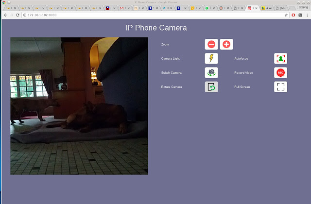
To stream video back to my laptop, I used the App IP Phone Camera by Deskshare. To link to it I simply point my browser to the Nexus 1's WiFi IP address and port 8080:

http://172.16.1.102:8080

Camera and platform is controlled from a laptop
 Typical front camera view:

Let sleeping dogs lie: will they be replaced by AI?
Rear-facing camera view:
MoboCam looks back ...
The nice thing about this is I get to postpone putting in encoders (and the attendant interfacing circuits), motor drives, control software and jump straight to the fun stuff.

The control commands are much the same (see previous blog post):

Command line interface: a proper GUI has yet to be done

 As usual, the smartphone is attached to the platform with a small cardboard box (the same one the Arduino parts came in), duct tape and scotch tape. The smartphone needs to be easily removed and mounted in order to start the app.

It needs to be reasonably rigid: positional accuracy is important to navigate the house. Barely one hour later, assembly was complete and MoboCam made its first remotely-controlled sortie from its birthplace: the study.

First sortie: MoboCam needs to traverse a corridor
It went down a 1m wide by 5m long corridor with no difficulty, mainly because it could center on the bright window at the end. Turn to the left and MoboCam sees its first light of day.

Light of day. Notice Mark I mobile alarm system on front guard duty.
The platform sorely needs two more wheels. It gets stuck very easily: even the thinnest doormats gets stuck on the front and back supports. And it would be nice to be able to reverse.

A dedicated program needs to be done to issue Piface commands on pressing the keyboard arrow keys. A surprising amount of turning was required to orientate myself.

The wheels needs encoders or tachometers to measure distance traversed. This makes it able to be programmed to travel to specific waypoints.

There you have it: the cheap Raspberry Pi robot platform becomes a camera carrier. Possibly applications are a telepresence robot, a mobile house alarm platform and best of all, a fun toy.

In case you are wondering, here is what a cheap Raspberry Pi robot looks like when it is not made from cardboard and duct tape: the Dexter Industries GoPiGo (USD200 or RM840):


GoPiGo3


Happy trails.

Monday, 9 October 2017

Arduino and the Robot

Arduino and the Robot Video (Youtube)

A few years ago, I bought a cheap plastic robot platform to play with. I bolted on two 12V geared motors, a Raspberry Pi with a WiPi WiFi USB dongle and a PiFace Digital,relay board and could drive the platform about. It trailed a 6m power cord. What I needed was a battery-powered system that actually lasted more than 5 minutes.

Unfortunately in 2011 I could not get lithium batteries easily, and so I used lead acid batteries instead. The batteries that were big enough were too heavy for the little platform and they cracked it. The few lithium batteries I had could not last long enough for the Raspberry Pi to power up.

The robot platform languished until I discovered recently power banks and Arduino parts are very cheap and you could buy them online. Enter the Arduino XL6009 5V to 12V converter:

The Arduino XL6009 costs a mere RM4.50
Together with a 20000mAh lithium power bank, which can cost as little as RM70 (I bought mine for RM87) I can now restart the robot platform project.

Rasberry Pi robot platform components (Raspi, Piface, WiPi, XL6009 and power bank) for assembly
Control and extra processing power for is from my Acer laptop. I expect to ssh via WiFi into the Raspi and execute the motor commands using a python script. The Piface relay board do nothing more than connecting 12V to the motors on command. Imaging, GPS and audio will be from an old onboard Android Nexus 1 smartphone, long put aside for a Nexus 5.

 The two motors are Cytron spg30-300k, rated at 12V 430mA (equivalent to 1032mA at 5V) each. Assuming the Raspberry Pi takes 160mA, that is 2224mA. The power bank should last 9 hours at full power. I expect the consumption to be a lot less mainly because it will be moving less mainly for the control program catches up. Anyway I do not expect the flimsy chassis to hold up for 9 hours.

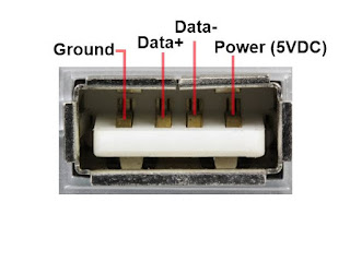
But first, the XL6009 needs to be set correctly. Wire up a USB connector to it. You can cut a USB cable and find the 5V and 0V lines by measurement. Or you can use this:

USB connector pinouts
Or if you have recently discovered Arduino, you could buy an Arduino USB connector breakout PCB for RM2.50:
 Connect the USB connector to the XL6009 inputs and set the potentiometer until you get the right voltage output. My XL6009 was preset to 24V so I had to do a fair number of turns to get it down to 12V.

Setting the XL6009. For convenience I have connected voltmeters to the input and output

The power bank has 2 USB output ports, one at 2A and the other 1A. I connected the 2A output to a Raspberry Pi with a Piface Digital Cape as well as the WiPi WiFi dongle. The assembly took some 400mA at startup and between 100-300mA after.

I first tested the program 'dry', without the motor 12V power. You can tell if the relays are clicking on - besides the sound, there is a corresponding output LED.

Next I connected up the XP6009 to the power bank 1A output. The first time I tried it crashed the WiFi connection to my laptop. It rebooted OK after. Next to reduce the load on the motors, I raised the wheels off the floor so they spun free.

The first time I pulsed the motors on for only 20ms, and that was enough to drag the power bank output down and crash the Raspberry Pi.

Despite lifting the wheels clear, the motor gears must still present a considerable load. I needed to reduce the motor current. 1A seems a nice round number, and if I put a 5R 5W resistor at the 5V input to the XL6009 this should do it. But I only have a 2R7 resistor, and in the interests of expediency I used that, but swapped the motor power to the 2A power bank output.

Raspberry Pi Robot platform, assembled in glorious duct tape
The program is simple. You need the C library supplied with the Piface.

root@piface1:/home/heong/piface/piface-master/c# cat forward.c
#include <libpiface-1.0/pfio.h>
#include <stdio.h>
#include <unistd.h>

int main(int argc, char* argv[])
{
  int ontime=300; /* milli-seconds */

  if ( argc != 2 )
  {
    printf("Usage: %s ms\n", argv[0]);
    _exit(1);
  }
  sscanf(argv[1], "%d", &ontime);
  pfio_init();
  pfio_digital_write(0, 1);
  pfio_digital_write(1, 1);
  printf("Sleeping %d milliseconds\n", ontime);
  usleep(ontime*1000);
  pfio_digital_write(0, 0);
  pfio_digital_write(1, 0);
  pfio_deinit();
}

The command to compile is:
 gcc -L/usr/local/lib/ -lpiface-1.0 -o forward forward.c

To run, you ssh into the Raspberry Pi:
ssh -t 172.16.xx.yy

I find a 200ms pulse produces a reasonable step:

./forward 200
Sleeping 200 milliseconds
For the great finale the wheels were lowered to the ground and the and the command was executed as many times as necessary.

A very simple mod would allow you to make right.c and left.c when direction changes are required. And free Android apps are available to trigger the Pi commands.

The mechanical bit leaves much to be desired: the heavy power bank did not sit square over the wheels, so a left turn is much easier than a right turn. It needed two more wheels rather than those noisy screw heads, and it wobbled horribly, shaking lose its connectors after a few minutes.

And yet, it finally managed to lose its power cord tether and it moved fast enough to alarm Sidney the cat.

There you have it, a cheap robot platform prototype 6 years in the making, finished in one weekend.

Apart from the shakey construction, the power bank needs to be down-rated, and the PiFace Digital needs to be swapped out for a proper motor driver. Given that the processing is done from a host via a wireless link, a Raspberry Pi is overkill; a bluetooth PIC18F14K50 should do.

So, back to the drawing board, back to the pachinko.  In the meantime I see a bright future for the first prototype as a back porch prowler, scuttling back to the solar battery to recharge when low.

Saturday, 7 October 2017

Heong, when is the prototype going to be finished?


I learned long ago, never to wrestle with a pig. You get dirty, and besides, the pig likes it.
- George Bernard Shaw


Blast from the past: the Macsym 150, running Macbasic was an early embedded computer

Back when I was at my first job designing SCADA systems for Oil & Gas installations, a new system perhaps took two to three years to complete. You got from the customer what he wanted in detail, the 'requirements', produced a massive document, the 'specifications' and then proceeded with the 'design', and then the hellish part, 'testing' and hopefully the delivery and installation. These days it is called the waterfall model.

This was so with my first project 1985-1987, a SCADA system to monitor 4 Daniel 2234 flow computers. It was based on the ancient MACSYM 150 by Analog Devices, both now extinct. While wallowing in the now-familiar post-project blues, I asked to tag along for the big one- a building automation system for a whole building complex comprising tower block, museum, theater and library. It was critical to the company- in fact the Technical Director handled it himself. Being the FNG, I had to promise not to touch anything.

Heavy metal- PDP-11/23+

It was based on a Digital Equipment PDP11/23, heavy metal in those days. It ran Ultrix. A BAS is not that different from a SCADA. It required microprocessor-based RTUs.

By 1987 the project was in trouble. The company by then could not afford to import the rest of the RTUs nor pay for the software, but was still bound by contract to deliver the BAS. The performance penalties alone would spell the end. Desperate times required desperate people- going three months without pay does things to you.

We had the nucleus of the BAS- the PDP11/23+, one MTU and 6 RTU, so we knew how it should work. There was no choice- we produced the remaining 4 MTUs and 25 RTUs, copied it lock stock and barrel. We installed it and got a shock reject from the customer - the system was too slow. Despite the agreed-upon 'Requirements', and 'Specifications'.

There was little time to think. All I had on hand were IBM PCs. I got the newest one, an IBM PC/AT. The only choice of OS was SCO Xenix/286 and I pretty much wrote the software on the fly, alternating between customer site and office. The result was a 4X improvement in speed, and we got it accepted by the skin of our teeth.

Small beer- IBM PC/AT
 We had taken a properly engineered system, replaced major components willy-nilly and got away with it! It was a one-off, we had dodged a bullet and it was time to go back to the straight and narrow, the waterfall method. I could not have been more wrong.

Over the years working at Westinghouse, HP, Motorola, then ON Semiconductor this pattern was to be repeated again and again. The waterfall method does not work.

So, what worked?

Being close to the customers did. You visited them often. Better yet get a desk there too. This is because often the customers does not know what they want. They know what they don't want- if they can see it and use it they will soon tell you.

You then need to whip up a prototype to show the customer. The faster the better. It does not have to meet all the requirements - the customers are certain to reject even the perfect ones. But nearly every time they will tell you why they hate it.

You then repeat the process - rush back to the office, and repeat the entire process and rush back to the customer with a new prototype. Eventually they will relent and you will succeed. Most customers are flattered you are willing to develop a bespoke system for them. In fact most times the customers do not get to meet the designers. They just keep hearing the mantra from the sales or operations guys: "You have agreed to the specifications and this is what we will deliver".

But what of the cost, the failed prototypes, the components discarded? There is no choice but to reduce cost throughout the process. The man-hours are about the same, the delivery times are often fixed in advance. You start with the components on hand. Failing that, off-the-shelf parts. You use the minimum of custom parts. Software is a godsend. There is little material cost and it can be changed very fast, often right there in front of the customer.

And that is why prototypes are never going to be finished. For there is always the next customer. Sometimes over many customers the design may settle to a happy equilibrium, and you get to declare victory and move on, but don't bet on it.

You will see this pattern repeated in this blog- the prototypes sort of work but there is always something lacking. If I am lucky this results in fresh insight on the design. It helps if you like design and prototyping. For me, this is pachinko - something done for fun. Like wrestling in the mud.

Over the years, especially in software, this method has been given respectability and names, 'iterative development', 'extreme programming'. You automate it up the wazoo and apply it to large teams(indeed the whole company), and it becomes 'DevOps'.

That used to be just my fangs out hair on fire approach, a beast to be let out only when necessary.

Happy Trails, and see you at the pachinko.

Bluetooth IoT Solar Battery Voltmeter Redux

From the last post we showed that the 3.3V TTL Arduino HC-06 can be mounted to an RS-485 USB PIC18F14K50  and be made to work. Here we add the analog input feature from another earlier post and hopefully the HC-06 will play nice. That was indeed the case, after a little persuasion.

Arduino HC-06 with RS-485 USB PIC18F14K50
This removed the need to use a Raspberry Pi for our Solar Battery Voltmeter and save 160mA of current consumption.

Mounted on the solar battery. The power adapter is a USB phone charger for use in a car cigarette lighter socket
The php script on the webserver simply executes the bluetooth master code directly, and the bluetooth link proved workable despite the webserver being inside the study with the doors and windows closed at least 10m away.

Despite the apparently simple task of integrating two features, caution is recommended. I modified a new RS-485 USB dongle for bluetooth and re-tested every time something new is added. The original working set is kept in case I needed a good set to test my software. Otherwise hardware and software errors tend to feed each other and you end up with an indigestible tangle.

First the new build was tested using easyhooks exactly like the previous post. Take care not to change the software at this point.

Next the bluetooth cable was assembled and the whole lot was retested. The HC-06 defaults to 9600 baud but the USB PIC18F14K50 starts up at 19200 baud. It was trivial for the Raspberry Pi to set the latter to 9600 baud, but without the Pi the PIC18F14K50 had to be made to power up at 9600 baud.

The analog input mod was then added. Here was a new wrinkle - when the analog code transmitted over the bluetooth channel somehow the result bytes fed back into the bluetooth receiver and triggered yet more transmissions. The PIC18F14K50 program was modified to only start analog input (and transmitting) only on receipt of the command 'z' and not just any keystroke.

The software is much the same as the last bluetooth post:

root@aspireE1:/home/heong$hciconfig
hci0:   Type: BR/EDR  Bus: USB
        BD Address: A4:DB:30:55:9C:AA  ACL MTU: 1022:8  SCO MTU: 183:5
        DOWN
        RX bytes:574 acl:0 sco:0 events:30 errors:0
        TX bytes:368 acl:0 sco:0 commands:30 errors:0

If you get nothing at this stage, you do not have a bluetooth controller, but if you get output like that above you go on to:

root@aspireE1:/home/heong$hciconfig hci up

If you check again your controller should read 'UP':

root@aspireE1:/home/heong$hciconfig
hci0:   Type: BR/EDR  Bus: USB
        BD Address: A4:DB:30:55:9C:AA  ACL MTU: 1022:8  SCO MTU: 183:5
        UP RUNNING
        RX bytes:1148 acl:0 sco:0 events:60 errors:0
        TX bytes:736 acl:0 sco:0 commands:60 errors:0

root@aspireF15:/home/heong$bluetoothctl
[NEW] Controller 00:15:83:15:A3:03 BlueZ 5.40 [default]
[NEW] Controller C8:FF:28:27:7D:2C BlueZ 5.40
[bluetooth]# devices
[bluetooth]# paired-devices
[bluetooth]# power on
[CHG] Controller 00:15:83:15:A3:03 Class: 0x00010c
Changing power on succeeded
[CHG] Controller 00:15:83:15:A3:03 Powered: yes
[bluetooth]# scan on
Discovery started
[CHG] Controller 00:15:83:15:A3:03 Discovering: yes
[NEW] Device 98:D3:32:20:BB:7B 98-D3-32-20-BB-7B
[CHG] Device 98:D3:32:20:BB:7B LegacyPairing: no
[CHG] Device 98:D3:32:20:BB:7B RSSI: 127
[CHG] Device 98:D3:32:20:BB:7B Name: HC-06
[CHG] Device 98:D3:32:20:BB:7B Alias: HC-06
[CHG] Device 98:D3:32:20:BB:7B LegacyPairing: yes
[CHG] Device 98:D3:32:20:BB:7B RSSI is nil
[bluetooth]# agent
Missing on/off/capability argument
[bluetooth]# agent on
Agent registered
[bluetooth]# default-agent
Default agent request successful
[bluetooth]# pair 98:D3:32:20:BB:7B
Attempting to pair with 98:D3:32:20:BB:7B
[CHG] Device 98:D3:32:20:BB:7B Connected: yes
Request PIN code
[agent] Enter PIN code: 1234
[CHG] Device 98:D3:32:20:BB:7B UUIDs: 00001101-0000-1000-8000-00805f9b34fb
[CHG] Device 98:D3:32:20:BB:7B Paired: yes
Pairing successful
[CHG] Device 98:D3:32:20:BB:7B Connected: no
[CHG] Device 98:D3:32:20:BB:7B Connected: yes

At which point we do:
root@aspireF15:/home/heong/mpg$rfcomm bind /dev/rfcomm0 98:D3:32:20:BB:7B 1

The python script (easily called by a webhost PHP script) is:
root@aspireF15:/home/heong/solar$cat analog_pic/bluetooth_solarbat.py
#!/usr/bin/python
import serial
from time import localtime, strftime, sleep

port=serial.Serial('/dev/rfcomm0', timeout=3)

if __name__ == "__main__":

  sleep(5)
  Vbat = ''
  port.write('z')
  Vbat= port.read(100)
  Battery_Voltage=int(format(ord(Vbat[0]), '02x'), 16)*256 + \
                  int(format(ord(Vbat[1]), '02x'), 16)
  if Vbat[2:5] != 'HCM':
    print 'HCM Checkbyte Fail', Vbat

# Calibrated_Battery_Voltage = Battery_Voltage * 13.75 / 689
  Calibrated_Battery_Voltage = (Battery_Voltage * 5.0) / 1024 # convert to floating point
  print 'Bluetooth power',
  print format(ord(Vbat[0]), '02x'),
  print format(ord(Vbat[1]), '02x')


  print Calibrated_Battery_Voltage,'Volts',strftime("%Y-%m-%d %H:%M:%S", localtime())

  Battery_Voltage=int(format(ord(Vbat[5]), '02x'), 16)*256 + \
                  int(format(ord(Vbat[6]), '02x'), 16)
  if Vbat[7:10] != 'LJP':
    print 'LJP Checkbyte Fail', Vbat

  for j in range(len(Vbat)):
    print format(ord(Vbat[j]), '02x'),
  print('\n')

# Calibrated_Battery_Voltage = Battery_Voltage * 12.56 / 640
  Calibrated_Battery_Voltage = Battery_Voltage * 13.75 / 689
  print 'Solar battery power',
  print format(ord(Vbat[5]), '02x'),
  print format(ord(Vbat[6]), '02x')
  print Calibrated_Battery_Voltage,'Volts',strftime("%Y-%m-%d %H:%M:%S", localtime())


Note the raw output is still printed at this stage to aid with calibration.
One of the analog inputs have been connected to the PIC18F14K50 input power (5V), as it might come in handy should I connect the setup directly to the solar panel output, bypassing the battery.

When executed the script should read:

root@aspireF15:/home/heong/solar$analog_pic/bluetooth_solarbat.py
Bluetooth power 03 f9
4.9658203125 Volts 2017-10-08 08:40:05
03 f9 48 43 4d 02 7f 4c 4a 50

Solar battery power 02 7f
12.7521770682 Volts 2017-10-08 08:40:05

There you have it, a solar battery voltmeter that only takes 30mA at 5V. A wireless IoT device makes a voltmeter lot safer to read, and gives us the confidence to later connect it to read much higher voltages- 100Vac, 240Vac, 340Vdc. Imagine dropping one of these babies into a 10KW inverter (used electric vehicles, escalator, elevator) to diagnose problems. Makes a change from poking at the charred remains trying to do the same.

I originally intended to post a link to the PHP script to read the battery voltage online, but for some reason bluetoothctrl would not run properly on my Beaglebone White webhost CPU nor my backup webhost, an older Acer laptop.

Which brings me to why I like using a full Linux installation as an embedded controller whenever I can. When prototyping, little niggles like this crop up all the time. With a full installation, this almost never become a show-stopper. This is because it is much easier to modify a full Linux installation than any system which has already been cut down, like busybox, uLinux or a dedicated embedded OS.

Happy trails.