Wednesday, 26 June 2019

Internet over Easy: TP-Link MR3420 as 3G Failover

The TP-Link MR-3420 takes a 3G USB Modem
(2020-01-22 Update): See here for an updated version.
The last six months I have been building and installing Internet of Things devices around the house and my nearby office. I run them from a single 8Mbps ADSL copper line from the Telekom Malaysia (TM), which connects to a TP-Link Archer D50 and which in turn acts as WAN for a TP-Link MR-3420. This provides ADSL with a failover to 3G.

TP-Link Archer D50 is a budget ADSL WiFi modem router

Now I did not really put much thought in selecting TP-Link or other models. They happened to be what was available in the Seremban stores over the years and I just happened to buy one. Or rather, a few, as I live on top of a little hill and the house tends to get struck by lightning a few times a year, usually killing the ADSL modem. I usually preset each modem with identical settings so that they can be swapped out in a few minutes.

If we are at home during a lightning storm we often disconnect the modem from the ADSL line as this seems to save it from getting destroyed in a strike. There is little to lose as the ADSL line often cuts out during an electrical storm anyway. When this happens, the MR-3420 fails over to a 3G connection using an MA260 3G USB dongle.

TP-Link MA260 3G USB dongle

The MR-3420 has an ADSL to 3G failover function:

MR-3420 ADSL to 3G failover
Now both the D50 and MR-3420 can put out WiFi hotspots but only the MR-3420 hotspot is backed up over 3G. This became really useful with the IoT devices because losing your Internet connection now meant losing access to your lights, fans and other IoT gizmos.

What's more being reliant on Google Assistant for reminders and note-taking makes you really feel the loss of an Internet connection. The failover to 3G is quite smooth and you really only notice a change in speed and responsiveness of the Internet. It costs me an extra RM29 a month for a basic 3GB data-only 3G connection.

When we went away for a week-long holiday we noticed that the MR-3420 reliably fails over, but will not fail back. Which means once it cuts over to the backup 3G line it will not cut back to the restored ADSL connection. This especially happens if the ADSL (ie WAN) connection went down but the network connection with the D50 is still up. Upgrading the firmware did not seem to help. However, disconnecting and reconnecting  the LAN cable to the D50 will result in a failback.

We used to get by 'failing back' by reconnecting the LAN cable by hand, but of late the ADSL has taken to intermittent disconnects several times a day. This pretty much leaves the MR-3420 in failover mode permanently and messing up our IoT chi.

Now I can probably buy a proper modem with 3G failover (and working failback!), but I am loath to junk electronics that still have life in them, especially having bought a few identical spare units. Ideally we get it to work by adding a little more junk ...

I have an orphaned Raspberry Pi Model B+ after having upgraded to the superlative Raspberry Pi 3 B+.

A picture of the Raspberry Pi B+ might seem redundant, but the various models can be hard to distinguish


 I also happened to have a Piface Digital 2, made redundant by those cheap ESP8266 relay boards.

PiFace Digital 2


And if I threw in a D-Link DES-1005A LAN switch, I can use traceroute to detect a restored ADSL connection to the D50 and use the Piface Digital 2 to power-cycle the LAN connection  (DES-1005A) between the D50 and the MR-3420. This should cause the MR-3420 to fail back.


D-Link DES-1005A uses a 5Vdc power supply
Now you can use any LAN switch you like, but the DES-1005A only requires 5Vdc at 60mA or so, which means the whole setup will run off the Raspberry Pi power supply (via a USB port). You can just as easily switch the mains power to the DES-1005A, but not having lethal voltages exposed (around the Piface connector) makes things a lot safer.

The D50 is necessary because the MR-3420 does not have an ADSL modem.

To prepare any Raspberry Pi, you just need to set it up with an Internet connection (in my case a D-Link DWA-123 USB WiFi dongle) and do:

# apt-get update
# apt-get upgrade

Next, using raspi-config I set it up to log into my D50 hotspot whose IP address for the purpose of this post is 'xx.xx.xx.1'. Next set up the Pi's Ethernet connection to the MR-3420, whose IP is 'yy.yy.yy.1'.  In your /etc/dhcpcd.conf add:

interface eth0
static ip_address=yy.yy.yy.2/24

interface wlan0
static ip_address=yy.yy.yy.2/24
static routers=yy.yy.yy.1
static domain_name_servers=8.8.8.8

Now set it so that access to 8.8.8.8 is routed via the TL-MR3420:

route add -host 8.8.8.8 gw yy.yy.yy.1 dev eth0
On reboot, your primary link to the Internet is now via the D50 WiFi hotspot. You are also linked to the MR-3420 via Ethernet. 

Now set up the Piface Digital 2. There is a slight hitch, but we can get it to work. Connect the DES 1005A LAN switch 5V line to Relay0:

Piface Digital 2 Pinout. Only Relay0 NC and CO are used
The 0V return line does not need to be switched.

The Piface Digital 2's program is simplicity itself;

# cat relay1.py
from time import sleep
import pifacedigitalio

DELAY = 2.0  # seconds

if __name__ == "__main__":
    pifacedigital = pifacedigitalio.PiFaceDigital()
    #  power-cycle LAN switch
    pifacedigital.leds[0].turn_on()
    sleep(DELAY)
    pifacedigital.leds[0].turn_off()

You run it using the command:

# python3 ./relay1.py

Now we will need to detect a failover condition. We try to connect to an always available server, say Google's DNS server 8.8.8.8. Now the Pi will default to using the D50 WiFi, so to force it to use Ethernet we do:
# route add -host 8.8.8.8 gw yy.yy.yy.1 dev eth0

The traceroute should now produce:
# traceroute 8.8.8.8
traceroute to 8.8.8.8 (8.8.8.8), 30 hops max, 60 byte packets
 1  yy.yy.yy.1 (yy.yy.yy.1)  0.768 ms  0.939 ms  0.612 ms
 2  xx.xx.xx.1 (xx.xx.xx.1)  0.893 ms  0.706 ms  0.630 ms
 3  115.134.254.254 (115.134.254.254)  40.218 ms  42.331 ms  43.880 ms
 4  10.55.106.61 (10.55.106.61)  53.481 ms 10.55.106.63 (10.55.106.63)  53.336 m
s  55.914 ms
 5  10.55.39.196 (10.55.39.196)  55.378 ms 10.55.39.146 (10.55.39.146)  55.988 m
s 10.55.39.196 (10.55.39.196)  57.889 ms
 6  10.55.48.64 (10.55.48.64)  61.153 ms 10.55.48.66 (10.55.48.66)  46.202 ms 10
.55.48.64 (10.55.48.64)  48.096 ms
 7  72.14.197.66 (72.14.197.66)  50.004 ms  51.596 ms  53.118 ms
 8  108.170.249.225 (108.170.249.225)  55.585 ms 108.170.249.241 (108.170.249.24
1)  46.389 ms 108.170.250.1 (108.170.250.1)  49.268 ms
 9  dns.google (8.8.8.8)  50.805 ms  52.660 ms  54.818 ms

Now we only need to look for the D50's IP address so this is sufficient:
# traceroute 8.8.8.8 | grep -w 'xx\.xx\.xx\.1'
 2  xx.xx.xx.1 (xx.xx.xx.1)  0.893 ms  0.706 ms  0.630 ms

Now if the above command produces nothing we now know we are in failover mode and we now need to check if the ADSL is restored. Here is the output of a restored D50:

# ping -c 4 -I wlan0 8.8.8.8 
PING 8.8.8.8 (8.8.8.8) from xx.xx.xx.2 wlan0: 56(84) bytes of data. 
64 bytes from 8.8.8.8: icmp_seq=1 ttl=57 time=57.1 ms 
64 bytes from 8.8.8.8: icmp_seq=2 ttl=57 time=52.6 ms 
64 bytes from 8.8.8.8: icmp_seq=3 ttl=57 time=51.4 ms 
64 bytes from 8.8.8.8: icmp_seq=4 ttl=57 time=49.1 ms 
--- 8.8.8.8 ping statistics --- 4 packets transmitted, 4 received, 0% packet loss, time 3005ms
rttmin/avg/max/mdev = 49.103/52.587/57.140/2.931 ms

Again, when there is no ADSL service there is no output. After confirming ADSL is back we just need to power cycle the DES-1005A LAN switch:

# python3 ./relay1.py

A bash script can do this:

# cat failover
#!/bin/bash
ADSL=$(traceroute 8.8.8.8 | grep -w 'xx\.xx\.xx\.1')
echo "result is "  $ADSL
if  [[ "$ADSL" == "" ]]
then
  date
  echo "Streamyx failed ..."
  ping -c 4 -I wlan0 8.8.8.8
  if [ $? == 0 ]
  then
    echo "Need to cut back!"
    python3 ./relay1.py
  fi
else
  echo "all's well"
fi

And for continuous operation:

# cat failover_loop
#!/bin/bash
echo on
while [ 1 ]
do 
  console_output=$(/home/heong/failover/failover)
  echo $console_output
  echo "Sleeping 60s"
  sleep 60
done


3G failback: from left, TL-MR3420 with MA260 3G dongle, Raspberry Pi with Piface 2 shield, DES-1005A LAN switch and Archer D50

And there you have it. MR-3420 failback. Internet over easy.

Note if you are a moderate Internet user you can get by with just the 3G line and you would not have to bother with this ADSL failover palaver. Or if you are blessed with a fiber optic connection, or any other service provider besides TM ... 

Happy Trails.

Tuesday, 25 June 2019

Piface Digital 2 Problem: The Case of the Reluctant Model (Updated 2020-01-16)

Erle Stanley Gardner's 'The Case of the Reluctant Model'
Before the ESP8266, I started off using old Linux laptops, then Raspberry Pis as IoT devices. If it fits the space, power or cost budget, why not? Especially when Linux is a natural for remote operation and runs on nearly everything.

Piface Digital for the Raspberry Pi Model A


I was an early user of the Piface Digital running on the Raspberry Pi Model A. While not the cheapest systems around, you get get IoT systems up up and running very fast, e.g., as motor driver for an IoT robot platform. In addition to the relay outputs, here are also inputs with very handy LED indicators. There was even a PiFace Digital 2 which lets you upgrade to a Raspberry Pi Model B:

Piface Digital 2 for the Raspberry Pi Model B
I bought my Digital 2 and, so it was quite a shock when early in the year I used it with my Raspberry Pi Model B+ and it did not work:

# python3 /usr/share/doc/python3-pifacedigitalio/examples/blink.py
Traceback (most recent call last):
  File "/usr/share/doc/python3-pifacedigitalio/examples/blink.py", line 9, in <module>
    pifacedigital = pifacedigitalio.PiFaceDigital()
  File "/usr/lib/python3/dist-packages/pifacedigitalio/core.py", line 82, in __init__
    self.init_board()
  File "/usr/lib/python3/dist-packages/pifacedigitalio/core.py", line 107, in init_board
    h=self.hardware_addr, b=self.bus, c=self.chip_select))
pifacedigitalio.core.NoPiFaceDigitalDetectedError: No PiFace Digital board detected (hardware_addr=0, bus=0, chip_select=0).

I found the manual from the Farnell website, and all the jumpers checked OK. A quick search of the Internet produced the first clue here. It looks to be an error in the new Piface software. An upgrade to Raspbian had changed the default SPI frequency to 10MHz which is too high for the PiFace Digital 2, so it stopped working out of the box.

This is really Piface's problem - it dropped the ball maintaining the software, but for now, Mike Richards has a good writeup on the solution, which is to get the latest update directly from the Piface github.

So I upgraded and found exactly the same problem! Dropping the ball seems to be getting to be a habit for Piface, or perhaps something went awry during the upgrade.

From the original link, I simply need to specify the SPI speed in the file spi.py. In my installation it came up as /usr/lib/python3/dist-packages/pifacecommon/spi.py

At line 65:
        # create the spi transfer struct
        transfer = spi_ioc_transfer(
            tx_buf=ctypes.addressof(wbuffer),
            rx_buf=ctypes.addressof(rbuffer),
            len=ctypes.sizeof(wbuffer)
        )

Change to
        # create the spi transfer struct
        transfer = spi_ioc_transfer(
            tx_buf=ctypes.addressof(wbuffer),
            rx_buf=ctypes.addressof(rbuffer),
            len=ctypes.sizeof(wbuffer),
            speed_hz=ctypes.c_uint32(15000) # 2019-06-25
        )

And now the example program works and LED7 lit up:

# python3 /usr/share/doc/python3-pifacedigitalio/examples/blink.py

That seems to conclude the Case of the Reluctant Piface Model 2. Later when I checked, the same problem recurs if you upgraded the software to a Piface Digital 1. The same solution applies.

(Update 2020-01-16)
The piface github repository has updated their code, and the proper solution is now:
        # create the spi transfer struct
        transfer = spi_ioc_transfer(
            tx_buf=ctypes.addressof(wbuffer),
            rx_buf=ctypes.addressof(rbuffer),
            len=ctypes.sizeof(wbuffer),
            speed_hz=ctypes.c_uint32(self.speed_hz)
        )

Sadly if you have an up-to-date version of Raspbian, the ugrade instructions no longer work:
$ sudo apt-get install python{,3}-pifacedigitalio
Instead, use:
 pip3 install pifacedigitalio
Or,
 pip install pifacedigitalio

Happy trails.

Tuesday, 28 May 2019

Pan/Tilt Head Using the NodeMCU L293D shield and TowerPro MG-996R Servomotor

Left: Dual TowerPro MG-996R, right: L293D NodeMCU ESp-12E Shield Click on picture for youtube video
I had always wanted a pan/tilt head. There is some deterrence value to the baleful gaze of a pan/tilt camera following your every move. While pan/tilt cameras are cheap and easily available, they are less useful at night: their range is a lot shorter.  It would be nice to move an LED torchlight together with the camera.

You could tape an LED torch onto your favorite IP camera, but the mechanism is often made of  plastic and the extra weight wears it out fast. A homebrew pan/tilt head would be nice ...

The L293D NodeMCU ESP-12E motor shield was such an easy build (see part 1, part 2, and part 3) I quickly bought two Towerpro MG-996R servomotors for just RM22.90 (about USD5) each and matching mounting brackets for RM10.30.

Towerpro MG-996R Servomotor

And matching accessories

The brackets were listed in lelong.com as:

"Arduino Multi Purpose Servo Motor Holder Bracket MG995 MG996"


Arduino Multi Purpose Servo Motor Holder Bracket MG995 MG996

I found the mechanical assembly work quite mystifying, but Starmaxtrek's youtube video was a godsend:

Click on picture for Youtube video on mechanical assembly
Documentation for the MG-996R took a little digging, but you can find a copy here.

For testing, I shorted VM to VCC on the L293D and powered everything from VCC using a USB smartphone charger.  The only change in the ESP-12E program was to change the PWM frequency to 50Hz:
  analogWriteFreq(50);

For my setup I found the servomotors reacted only to PWM values between 1-25%. The shaft rotated some 120 degrees and the pan/tilt head whirred about with a gentle menace.

The youtube video is here.

Life is good - Happy Trails.

Thursday, 16 May 2019

PWMing the ESP8266 - Programming: Part 3 of 3

L293D motor shield for NodeMCU ESP-12E. Note green 5V jumper supplying test power to L293D IC. Click on the picture for youtube video. 
In Part 2 I built a DC motor speed controller cum LED light dimmer with the parts I had on hand, mainly so I did not have to wait to test my software. In due course the part arrived: the L293 motor control shield for the ESP8266 NodeMCU ESP-12E development board. It cost me only RM10 (about USD2). The build quality was a little rough; I had some difficulty mounting the ESP-12E into the socket, but it worked as advertised.

L293D motor control shield


Tony Kambourakis has an excellent writeup on the L293D, so please head over there for details.

While testing the program I set the 5V USB power to drive the L293D by shorting VM to VIN, and connecting VIN to my Android smartphone charger. Try not to use the laptop/desktop USB port- it minimizes the damage should things go wrong. Be sure to remove the Vin-VM short when you progress to 12-36VDC. VIN still needs to be at 5VDC.

I only had to make a slight change to my program: the ULN2003 used different pins for PWM and added 2 GPIO pins for motor direction control. We do not really need to change the fan rotation direction, plus reversing power to LED lights may cause them not to turn on, so the additional GPIO pins are used to lock in the output pin assignments on the shield.

The http interface allows for easy webhooking into Google Home/Google Assistant for Voice Control.

#include <ESP8266WiFi.h>

const char* ssid = "YourAccessPoint";    
const char* password = "YourPassword";
IPAddress staticIP(123,45,67,89); // Change IP to suit your AP
IPAddress gateway(123,45,67,1);  
IPAddress subnet(255,255,255,0);
WiFiServer server (8080);
uint8_t PWMpin1 = D1;
uint8_t PWMpin2 = D2;
uint8_t Dirpin1 = D3;
uint8_t Dirpin2 = D4;

void setup ()
{
  delay (10);
  Serial.begin (115200);
  analogWrite(PWMpin1, 0);  /* set initial duty cycle */
  analogWrite(PWMpin2, 0);  /* set initial duty cycle */
  pinMode(Dirpin1, OUTPUT);
  pinMode(Dirpin2, OUTPUT);
  digitalWrite(Dirpin1, 1); // 2019-05-15 set output polarities to conform to shield
  digitalWrite(Dirpin2, 1);
  analogWriteFreq(10);    /* default is 1KHz range is 1Hz-1000kHz */

  // Connect to WiFi network
  Serial.println();
  Serial.println();
  Serial.print("Connecting to ");
  Serial.println(ssid);

  WiFi.mode(WIFI_OFF); // wifi reconnect workaround
  WiFi.mode(WIFI_STA);
  WiFi.begin(ssid, password);
  WiFi.config(staticIP, gateway, subnet); // Static IP. Not required for dhcp
  while (WiFi.status() != WL_CONNECTED) {
    delay(500);
    Serial.print(".");
  }
  Serial.println("");
  Serial.println("WiFi connected");
  Serial.print("Static IP address: ");
  Serial.println(WiFi.localIP());

  // Start the server
  server.begin();
  delay(50);
}

static int dots = 0;
static int val = 0; // 2018-10-25
static int val2 = 0; // 2019-04-19
static int commas = 0;
static unsigned long timeNow = 0; // 2019-03-17
static unsigned long timeLast = 0;
static int seconds = 0;

uint16_t dutycycle = 0; /* Set PWM duty cycle */

void loop() {

  // 2019-03-17
  timeNow = millis()/1000; // the number of milliseconds that have passed since boot
  if (timeLast==0 || timeNow<timeLast)
    timeLast = timeNow; // Start with time since bootup. Note millis() number overflows after 50 days
  seconds = timeNow - timeLast;//the number of seconds that have passed since the last time 60 seconds was reached.

  // 2019-02-24 Check for broken wifi links
  if (WiFi.status() != WL_CONNECTED) {
    delay(10);
    // Connect to WiFi network
    Serial.println();
    delay(10);
    Serial.print("Reconnecting WiFi ");
    delay(10);
    WiFi.mode(WIFI_OFF); // 2018-10-09 workaround
    WiFi.mode(WIFI_STA);
    WiFi.begin(ssid, password);
    WiFi.config(staticIP, gateway, subnet); // Static IP. Not required for dhcp

    while (WiFi.status() != WL_CONNECTED) {
      Serial.print("x");
      delay(500);
      dots++;
      if (dots >= 1000)
      {
        dots = 0;
        Serial.println("Giving up! Waiting for WDT reset ...");
        delay(20);
        while (1)
        {}
      }
    }
    Serial.println("");
    delay(10);
    Serial.println("WiFi reconnected");

    // Start the server
    server.begin();
    Serial.println("Server restarted");
    delay(10);
    // Print the IP address
    Serial.print("IP address: ");
    delay(10);
    Serial.println(WiFi.localIP());
    delay(10);
  }

  // Check if a client has connected
  WiFiClient client = server.available();
  if ( ! client ) {
    return;
  }

  //Wait until the client sends some data
  while ( ! client.available () )
  {
    delay (10); // 2019-02-28 reduced from 100
    Serial.print(".");
    if (commas++ > 5) {
      commas = 0;
      Serial.println("Terminating client connecting without reading");
      delay(20);
      client.stop();
      return;
    }
  }

  client.setTimeout(3000); // 2019-03-19
  Serial.println("new client connect, waiting for data ");

  // Read the first line of the request
  String req = client.readStringUntil ('\r');
  client.flush ();

  // Match the request
  String s = "";
  // Prepare the response
  if (req.indexOf ("/pwm1") != -1) // first channel
  {
    Serial.println("Command for PWM1 received");  

    int value_index = req.indexOf("/pwm1/");// Here you get the index to split the response string where it says "pwm1"
    String value_string = req.substring(value_index);
    String value = value_string.substring(6, value_string.indexOf("\r"));// Skip first 6 characters, get value
    Serial.println(value);
 
    s = "HTTP/1.1 200 OK\r\nContent-Type: text/html\r\n\r\n<!DOCTYPE HTML>\r\n<html>\r\nValue entered ";
    s += value;
    s += "\n\r";
    val = value.toInt();
 
    if (val < 0) // 2019-04-19 value must be 0-100%
      val = 0;
    else if (val > 100)
      val = 100;
    s += "Duty cycle (percent) used is: ";  
    s += String(val);
    s += "\n\r</html>\n";
    client.print (s);
 
    Serial.print("Duty cycle (percent) used is: ");
    Serial.println(val);

    dutycycle = (val * 1023) / 100; // Convert to 16-bit unsigned
    analogWrite(PWMpin1, dutycycle);
 
  } else if (req.indexOf ("/pwm2") != -1) {
      Serial.println("PWM2 command received");  

      int value_index = req.indexOf("/pwm2/");// Here you get the index to split the response string where it says "pwm1"
      String value_string = req.substring(value_index);
      String value = value_string.substring(6, value_string.indexOf("\r"));// Skip first 6 characters, get value
      Serial.println(value);

      s = "HTTP/1.1 200 OK\r\nContent-Type: text/html\r\n\r\n<!DOCTYPE HTML>\r\n<html>\r\nValue entered ";
      s += value;
      s += "\n\r";
      val2 = value.toInt();
 
      if (val2 < 0) // 2019-04-19 value must be 0-100%
        val2 = 0;
      else if (val2 > 100)
        val2 = 100;
      s += "Duty cycle (percent) used is: ";  
      s += String(val2);
      s += "\n\r</html>\n";
      client.print (s);
 
      Serial.print("Duty cycle (percent) used is: ");
      Serial.println(val2);

      dutycycle = (val2 * 1023) / 100; // Convert to 16-bit unsigned
      analogWrite(PWMpin2, dutycycle);
  } else if (req.indexOf("/index.html") != -1) {
      s = "HTTP/1.1 200 OK\r\nContent-Type: text/html\r\n\r\n<!DOCTYPE HTML>\r\n<html>\r\nStatus: PWM1 ";
      s += String(val);
      s += "% PWM2 ";
      s += String(val2);
      s += "%\r\n</html>\n";
      client.print (s);
      Serial.println("Status command received");
  }  
  else {
    Serial.println("invalid request");
    s = "HTTP/1.1 200 OK\r\nContent-Type: text/html\r\n\r\n<!DOCTYPE HTML>\r\n<html>\r\nInvalid request</html>\n";
    client.print (s);
  }

  delay (10);
  client.stop(); // 2019-02-24
  Serial.println("Client disonnected");
  delay(10);
}

And that was it- it worked first time. Having said that do test your system is stages: at first with no power to the L293D while you worked out the bugs in the program, and then with low (5V current-limited) power from the USB power supply. You can check the motor output pins with a voltmeter for polarity before connecting up the fan and LED lamp. 

I also use a 60W 230Vac mains isolation transformer for safety - it limits mains power in case of catastrophic failures. 

My test setup: clockwise from top left: isolation transformer, LED lamp, phone charger as 5V supply, ancient 12VDC power adapter, smartphone with chrome browser, ESP-12E with L293D motor shield, and 12VDC fan. Click on picture for youtube video.

On the smartphone browser, I used:
http://123.45.67.89:8080/pwm1/100

On my Linux desktop I used 
lynx -dump -read_timeout=5 -cmd_script=./lynx_script http://123.45.67.89:8080/pwm2/0

Make sure the phone or desktop is logged into the same WiFi access point. Notice the IP address here does not really work- they are not even Class C (ie your AP will not use them) so substitute your own.

There you have it: IoT PWM DC fan and LED lamp controller, all set for Google Home Voice Control. It cost me only RM30 (about USD8) per unit. Making electronics stuff can be cheap, fun and fast.

Happy Trails.

Wednesday, 24 April 2019

PWMing the ESP8266 Part 2 of 3: Building the Board

ESP-12E ESP8266 NodeMCU with ULN2003 Darlington IC provides PWM for 12Vdc devices like LED Lantern and DC Fan
Link to youtube video.

In Part 1, we saw that it was fast and easy to test Pulse Width Modulation (PWM) using an ESP8266-based NodeMCU ESP-12E development kit. To control a real device we increase the power rating of the ESP-12E's output pins D5 and D6 from 3.3V to 12V using darlington transistors.

Since we are all about fast and cheap prototyping, a handy darlington is the ULN2003. It is actually 7 darlingtons in a 16-pin package but is rated 50Vdc at 500mA and is cheaper than many single (ie discrete) darlington transistors.

ULN2003 is actually 7 Darlington Transistors
We will need a blank solder-able prototyping PCB - veroboard, stripboard, breadboard. Don't be afraid to try a little soldering- all you need is practice. Bob Pease, the legendary electronics guru, used to say, "My favorite programming language is solder".

Prototyping PCB
Bob "My favorite programming language is solder" Pease

Notice I have used an IC socket for the ULN2003- when dealing with motors and high voltages, mishaps are to be expected; it may need to be changed in a hurry. Notice the socket is only a 6-pin DIP originally meant for optical isolator ICs. This means I am only using 2 out of the 7 darlingtons. Feel free to cut off the dangling IC legs or even better simply turn them up out of harm's way. The extra metal helps to dissipate heat from the darlingtons.

Live bugs: ULN2003 and ESP-12E assembled on prototype board
Same board, solder-side. 

Also I only soldered 3 pins of the ESP-12E board, plus an extra 3 pins at each corner for mechanical strength. This makes it easy to de-solder the ESP-12E for other projects.

There are 3 pairs of wires: one for 12V DC power supply, and one each for each of the two PWM outputs. The idea is to tie one end of the load (fan, LED, etc) to 12V and the other to the darlington output so that the ESP8266 and turn it off and on at will.

I really should have used different colored wires for each pair but I did not have enough wires of the correct gauge, so had to make do with a little duct tape and marker pen.

PWM output wires are 12V (red) and darlington collector (black)
 For a long and happy life for the ULN2003 while driving inductive loads like DC motors, I have also connected a 12V 1W zener diode, forward-biased from 12V to pin 9. It is a little counter-intuitive but you are strongly encouraged to read Douglas W Jones' venerable work on stepper motor drivers, using among others the ULN2003. 

Douglas W Jones: his kung-fu is strong ...

To minimize damage from wiring mistakes and the like, first check the unpowered, unconnected board for short-circuits, especially between 3.3V and GND, 5V and GND and 12V and GND. Next check for ESP-12E and ULN2003 shorts to 3.3V, GND and 12V. 

When testing, it is advisable to first not to connect to 12V power and just test with a power bank. Then test with 12V on. If it works well enough test with a powered USB hub rather than directly from your laptop/desktop. If you must test with a desktop try using a USB port from a PCI daughter card rather than from the mainboard. This is to avoid damaging expensive kit like laptops, desktops and servers.

There you have it, a PWM board you can build in half a day. It can control DC devices up to 50V at 500mA like CPU cooling fans, LED lights, and alarm sirens. 

Happy trails.

Friday, 19 April 2019

PWMing the ESP8266 Part 1 of 3

Pulse Width Modulation can be used to dim LED lights and set DC motor speed
Link to youtube video.

Some time ago, the dual fans on my laptop stand froze solid. I had been re-purposing old laptops as IoT servers and running them 24/7 wore out the internal CPU fans, so I ventilated the bottom with a dual-fan laptop stand.

Laptop stand with dual slow fans
That lasted only a few months. Fans have a surprisingly low temperature rating, often lower than that of a CPU. A failing fan will slow down causing the CPU temperature to rise, which further shortens fan life. So the trick is not to overheat the fan (the CPU is usually tougher).  I would rather replace the fans in the stand - it is much harder to replace the one in the laptop. So, I replaced the weedy 5V USB fans and shoehorned in two 12V 80mm x 800mm power supply ball-bearing fans.

Take this, hot stuff
This sorted the immediate problem: the laptop runs a lot cooler but it is also a lot noisier. If I left the study door open the wife would think the kettle has been left on. And, the increased vibration cannot be good for the laptop.

Pulse-Width Modulation can be used to control fan speed by turning off its power some of the time. And making an IoT PWM device would be a nice project.

Using the Linux command sensors I can even detect the CPU temperature and speed up the fan accordingly with a bash shell:

$sensors
coretemp-isa-0000
Adapter: ISA adapter
Package id 0:  +63.0°C  (high = +100.0°C, crit = +100.0°C)
Core 0:        +63.0°C  (high = +100.0°C, crit = +100.0°C)
Core 1:        +60.0°C  (high = +100.0°C, crit = +100.0°C)

nouveau-pci-0100
Adapter: PCI adapter
GPU core:     +0.60 V  (min =  +0.60 V, max =  +1.20 V)

With DevOps, continuous improvement is the thing, so there is no need to have an all-singing all-dancing system done in one go. Instead we aim always for a working set of hardware and software, and to make sure little can go wrong, we implement the barest minimum, ie we start off with the smallest set of features we can.This means just the PWM.

ElectronicWings has a good writeup, and I will not replicate it here. There is minimal hardware (wiring) involved. The PWM output is indicated by the brightness of the LED.

Look, Ma, no soldering: Eazyhooks and PVC terminals are used to connect an LED and 330R resistor to the ESP-12E's D6 pin


The program is equally simple:

uint8_t LEDpin = D6; /* By default PWM frequency is 1000Hz and we are using same for this application hence no need to set */ void setup(){ Serial.begin(9600); analogWrite(LEDpin, 512); /* set initial 50% duty cycle */ } void loop(){ uint16_t dutycycle = analogRead(A0); /* read continuous POT and set PWM duty cycle according */ if(dutycycle > 1023) dutycycle = 1023;/* limit dutycycle to 1023 if POT read cross it */ Serial.print("Duty Cycle: "); Serial.println(dutycycle); analogWrite(LEDpin, dutycycle); delay(100); }

Instead of obtaining dutycycle from analogRead() I simply hardcoded a value between 0 and 1023 and reprogrammed and re-ran the ESP-12E a few times. This meant I did not need to wire up the trimpot. And since the difference in brightness can be a little hard to distinguish between reprograms, I modified it slightly so it changed dutycycle every 1.5s:

uint8_t LEDpin = D6;

/*
 *
   By default PWM frequency is 1000Hz and we are using same
   for this application hence no need to set
 
   https://www.electronicwings.com/nodemcu/nodemcu-pwm-with-arduino-ide
 */

void setup(){
  Serial.begin(115200);
  analogWrite(LEDpin, 1);  /* set initial duty cycle */
  analogWriteFreq(10);    /* default is 1KHz range is 1Hz-1000kHz */
}

uint16_t dutycycle = 0; /* Set PWM duty cycle */

void loop(){
  if(dutycycle > 1023) dutycycle = 1023;/* limit dutycycle to 1023 if POT read cross it */
  Serial.print("Duty Cycle: ");  Serial.println(dutycycle);
  analogWrite(LEDpin, dutycycle);
  delay(10000);
  if (dutycycle < 1023)
    dutycycle += 100;
  else
    dutycycle = 0;
}

And there you have it, PWM on the ESP8266-based NodeMCU ESP-12E board. Took hardly an hour. In Part 2, we will connect it to the cooling fans and in Part 3 set it up to webhook into Google Assistant.

Happy Trails.

Monday, 8 April 2019

Putting the ESP8266 to Sleep

Your pins are feeling heavy ... you shall enter a Deep Sleep ...
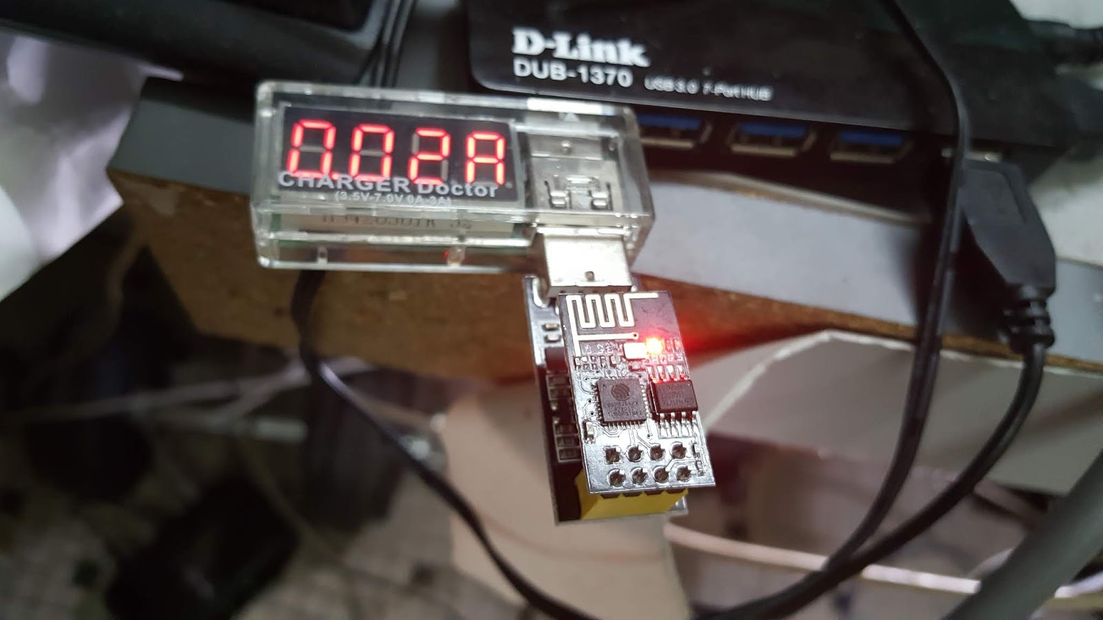
The ESP8266 is not exactly a low-power device and you really feel it when you are running it from a battery. An ESP-01S can draw up to 70mA when connected to its Access Point. A 3000mAh power bank will not last 2 days at that rate. Even doing nothing, the ESP-01S in program mode draws 20mA

Idle ESP-01S draws 20mA


Putting it to sleep can reduce the current to less than 1mA as this excellent link from randomnerd shows.. Now we're talking! but this usually means the bare board - randomnerd even removed the power LED to save those extra mA. Most applications require a little more peripherals so even if my current draw is 7mA my 3000mAh power bank will now last 18 days instead of 2, which is good enough for a start.

randomnerd's writeup is pretty much complete - I will not repeat his work here. The first test using the ESP-12E was done in less than an hour. I only had to connect D0 to RST.

ESP-12E all wired up for deep sleep. Notice the active current draw of 60mA


I used a cheap little USB ammeter for no other reason than it was handy and convenient, but it had a resolution of only 10mA. The ESP-12E current draw dropped from 60mA to 'zero' (ie less than 10mA) in deep sleep.

Thus encouraged, I soldered the wire required for the ESP-01S. But unlike randomnerd, rather than entering deep sleep the ESP-01S continually rebooted. This doesn't mean randomnerd gave bad advice. As usual with these cheap boards, your milage may vary.

Wiring D0/GPIO16 directly to ESP-01S RST pin did not work


The answer here sounded convincing: D0/GPIO16 floats high when in deep sleep and this can trigger RST which wakes up the ESP8266 who then runs its program and goes back to sleep and so on. The recommendation was for a 470Ohm resistor in series. I happened to have a 560Ohm one so in it goes:


Adding a 560-Ohm resistor in series worked

And work it did. I like the ESP-12E well enough but the ESP-01S is just so easy to package. Time to put it to good use.

And immediately found a gotcha- when it wakes from deep sleep it is equivalent to a hard reset. This means it no longer has its volatile memory (RAM). This makes things a little tricky if the ESP-01S had to drive an output like a relay or a transistor.

Now it will be still handy as an IoT input device running on battery. It wakes up, say every 5 minutes, connect to the access point, takes a reading of its sensor, say the room temperature, or a door magnetic switch and publish it to an MQTT server. The server acts as its non-volatile memory and with a little luck we might be even be able to finesse an IoT output by reading the MQTT subscription and re-initializing its output before the load realizes it. This will depend on whether the relay board is able to hold its output with the ESP-01S in deep sleep.

So in a fit of optimism, fired up by success so far, I got out a 1-channel relay PCB.

Notice the maximum current draw is 130mA with the ESP-01S awake and the relay on
The current draw of the ESP-01S with the relay on is 130mA. Now it does not make complete sense to drive an IoT relay output from a battery. Often the load will need power as well and may may draw precious mA from the battery.

The program is:

#include <ESP8266WiFi.h>
#include "RemoteDebug.h" // 2019-04-08 https://github.com/JoaoLopesF/RemoteDebug
RemoteDebug Debug;
#define HOST_NAME "esp01s-1relay"

const char* ssid = "YourAP"; // For testing in study
const char* password = "YourPassword";

IPAddress staticIP(12,34,56,78); // for testing in study only
IPAddress gateway(12,34,56,1); // for testing in study only
IPAddress subnet(255,255,255,0);

// Create an instance of the server
// specify the port to listen on as an argument
WiFiServer server(8080);

static int count = 0;
void setup() {
  Serial.begin(115200);
  delay(10); // 2018-10-08
  Serial.setTimeout(2000); // 2019-04-08
  pinMode(0, OUTPUT); // 2018-10-25 set gpio to o/p
  digitalWrite(0, 0); // Default to 'off' state to save power. relay board starts up with relay 'on'
  delay(10);

  // Connect to WiFi network
  Serial.println();
  Serial.println();
  Serial.print("Connecting to ");
  Serial.println(ssid);

  WiFi.mode(WIFI_OFF); //workaround 2018-10-08
  WiFi.mode(WIFI_STA);
  WiFi.begin(ssid, password);
  WiFi.config(staticIP, gateway, subnet); // Static IP. Not required for dhcp

  while (WiFi.status() != WL_CONNECTED) {
    delay(1000);
    Serial.print(".");
    count++;
    if (count >= 300) // 5 minutes==300s
    {
      count = 0;
      Serial.println("setup() giving up trying to connect to AP! waiting for WDT reset ... see you in 5min");
      delay(20);
      while (1)
      {}
    }
  }

  Serial.println("");
  Serial.println("WiFi connected");


  String hostNameWifi = HOST_NAME; // 2019-04-08 for remote debug
  hostNameWifi.concat(".local");
  WiFi.hostname(hostNameWifi);
  Debug.begin(HOST_NAME); // Initialize the WiFi server
  Debug.setResetCmdEnabled(true); // Enable the reset command
  Debug.showProfiler(true); // Profiler (Good to measure times, to optimize codes)
  Debug.showColors(true); // Colors

  // Start the server
  server.begin();
  Serial.println("Server started");
  debugI("Starting http server ...");
  delay(50); // 2018-10-25

  // Print the IP address
  Serial.println(WiFi.localIP());
  Debug.handle();
  yield();
}

static int dots = 0;
static int val = 0; // 2018-10-25
static int commas = 0;

void loop() {
  // 2019-02-27 Check for broken wifi links
  if (WiFi.status() != WL_CONNECTED) {
    delay(10);
    // Connect to WiFi network
    Serial.println();
    delay(10);
    Serial.print("Reconnecting WiFi ");
    debugI("Reconnecting WiFi ");
    delay(10);
    WiFi.mode(WIFI_OFF); // 2018-10-09 workaround
    WiFi.mode(WIFI_STA);
    WiFi.begin(ssid, password);

    while (WiFi.status() != WL_CONNECTED) {
      Serial.print("x");
      debugI("x");
      delay(500);
      dots++;
      if (dots >= 1000)
      {
        dots = 0;
        Serial.println("Giving up! Waiting for WDT reset ...");
        debugI("Giving up! Waiting for WDT reset ...");
        delay(20);
        yield();
        delay(20);
        while (1)
        {}
      }
      yield();
    }
    Serial.println("");
    delay(10);
    Serial.println("WiFi reconnected");
    debugI("WiFi reconnected");
 
    // Start the server
    server.begin();
    Serial.println("Server restarted");
    debugI("Server restarted");
    delay(10);
    // Print the IP address
    Serial.print("IP address: ");
    delay(10);
    Serial.println(WiFi.localIP());
    delay(10);
    Debug.handle();
  }

  // Check if a client has connected
  WiFiClient client = server.available();
  if (!client) {
    delay (10); // 2018-10-25
    //Serial.println("server not available!");
    // Serial.print("."); // no harm but too many dots
    delay(20);
    Debug.handle();
    return; // 2019-02-27 missing return
  }

  // Wait until the client sends some data
  Serial.println("new client");
  debugI("new client");
  while(!client.available()){
    delay(10); // 2019-02-28
    //Serial.println("client not available!");
    Serial.print(",");
    debugI(",");
   if (commas++ > 5) { // 2019-02-28
      commas = 0;
      Serial.println("Terminating client connecting without reading");
      debugI("Terminating client connecting without reading");
      delay(20);
      client.stop();
      Debug.handle();
      yield();
      return;
    }
    Debug.handle();
  }

  // Read the first line of the request
  String req = client.readStringUntil('\r');
  Serial.println(req);
  client.flush();

  // Match the request
  String s = "";
  // Prepare the response
  if (req.indexOf("/gpio/0") != -1) {
    val = 0;
    // Set GPIO2 according to the request
    digitalWrite(0, val);

    s = "HTTP/1.1 200 OK\r\nContent-Type: text/html\r\n\r\n<!DOCTYPE HTML>\r\n<html>\r\nRelay is now ";
    s += (val)?"on":"off";
    s += "</html>\n";
    debugI("relay off");
  }
  else if (req.indexOf("/gpio/1") != -1) {
    val = 1;
    // Set GPIO2 according to the request
    digitalWrite(0, val);

    s = "HTTP/1.1 200 OK\r\nContent-Type: text/html\r\n\r\n<!DOCTYPE HTML>\r\n<html>\r\nRelay is now ";
    s += (val)?"on":"off";
    s += "</html>\n";
    debugI("relay on");
  }
  else if (req.indexOf("/sleep/") != -1) {
    int value_index = req.indexOf("/sleep/");    // Here you get the index to split the response string right where it says "value"
    String value_string = req.substring(value_index);
    String value = value_string.substring(7, value_string.indexOf("\r"));   // Here you ignore the first nine characters of the substring ("-v-a-l-u-e-"-: ), then get the value, then ignore the rest of the string after the comma.
    Serial.println(value);
    s = "HTTP/1.1 200 OK\r\nContent-Type: text/html\r\n\r\n<!DOCTYPE HTML>\r\n<html>\r\nValue is now ";
    s += value;
    s += "</html>\n";
    val = value.toInt();
    debugI("Sleeping for %ds", val);
    //char valueless[80];
    //value.toCharArray(valueless, 80);
    //debugI("Sleeping for %s\n", valueless);
  }
  else if (req.indexOf("/index.html") != -1) {
    s = "HTTP/1.1 200 OK\r\nContent-Type: text/html\r\n\r\n<!DOCTYPE HTML>\r\n<html>\r\nRelay is ";
    s += (val)?"on":"off";
    s += "</html>\n";
    debugI("relay state is %d\n", val);
  }
  else {
    Serial.println("invalid request");
    s = "HTTP/1.1 200 OK\r\nContent-Type: text/html\r\n\r\n<!DOCTYPE HTML>\r\n<html>\r\nInvalid request</html>\n";
    debugI("invalid request");
  }
  Debug.handle();
  yield();
  client.flush();

  // Send the response to the client
  client.print(s);
  delay(10);
  client.stop(); // 2019-02-27
  Serial.println("Client disonnected");
  delay(10);
  // The client will actually be disconnected
  // when the function returns and 'client' object is detroyed
  if (val>1) {
    debugI("Sleeping for %ds", val);
    Serial.print("Sleeping for ");
    Serial.println(val);
    Debug.handle();
    delay(20);
    ESP.deepSleep(val); // 2019-04-08
  }
}


I have included Joao Lopes' Remote Debug code, as once mounted on the relay board it was difficult to get debug messages. You just do:

telnet 12.34.56.78

The program starts up with the relay off and initially draws 60mA. When the relay is turned on the system draws another 60mA. The deep sleep function is ESP.deepSleep(val) . On calling it, the current draw went from 120mA to 60mA.  To turn on the relay, you use a browser or the lynx command:

$lynx -read_timeout=5 -dump -cmd_script=./lynx_script http://12.34.56.78:8080/gpio/1
   Relay is now on

To sleep 30 seconds you specify the time in microseconds:

$lynx -read_timeout=5 -dump -cmd_script=./IoT/lynx_script http://12.34.56.78:8080/sleep/30000000
   Value is now 30000000 HTTP/1.0

The relay board proved unable to hold its last state when the ESP-01S goes into deep sleep. When deepSleep() is called the relay turns on. This resulted in the same current draw of 60mA. The 60mA saved by the deep sleep is taken up by the relay coil current. But dropping the relay state on deep sleep is a deal breaker for most applications.

Time to try the 2-channel relay. You can get it on ebay here. It has its own microprocessor, which should mean it can hold its state without the ESP-01S. The ESP-01S turns on the relays using the serial port. In the program you just replace code like:
    digitalWrite(0, val);
with

//Hex command to send to serial for close relay
byte relON[]  = {0xA0, 0x01, 0x01, 0xA2};
//Hex command to send to serial for open relay
byte relOFF[] = {0xA0, 0x01, 0x00, 0xA1};
//Hex command to send to serial for close relay
byte rel2ON[]  = {0xA0, 0x02, 0x01, 0xA3};
//Hex command to send to serial for open relay
byte rel2OFF[] = {0xA0, 0x02, 0x00, 0xA2};

    Serial.write (relON, sizeof(relON));

And sure enough it works. With the ESP-01S running and the relays off, it draws 70mA, about the same as the 1-channel relay board. With the ESP-01S in sleep mode it draws less than 10mA.

Dual Relay PCB with uP serial control. Note less than 10mA current draw in deep sleep

With everything running and both relays on, the current draw is 190mA. With ESP-01S now put to deep sleep, the relays retain their state and the system draws 120mA. More importantly when it wakes up, the relay state is still retained (although the ESP-01S will not remember this and has to subscribe to MQTT to find out).

Maximum power: 190mA with both relay and ESP-01S on

This is actually the ideal setup for my Google Voice activated IoT Autogate. The original version used 230Vac for power. Now I can use the autogate 12V backup battery. In the event of a power cut (happens a lot in my house but that is another story), I was afraid the IoT would drain the battery. Now I can simply put it to sleep. To use voice activation during a power cut, I simply set the sleep timer for 5 minutes. The command would be saved in the MQTT server feed and would be read by the ESP-01S when it wakes up. Even better, the autogate uses command pulses, so the relays are never active for more than 1 second.

There you have it: doing good while in deep sleep. Just goes to show in electronics, sometimes you can have your cake and eat it. Happy Trails.