Tuesday, 27 July 2021

The Little Computer that Could: YOLO Object Recognition and Raspberry Pi Part 2 of 3


You Only Look Once

One cure for motion detector false alarms in Part 1 is object recognition; the alarm is only raised if the intruder is recognized. YOLO is fast, trendy (deep neural net!) and will run on a Raspberry Pi. arunponnusamy comes straight to the point.

I already had numpy and openCV from Part 1, so it is just

# wget https://pjreddie.com/media/files/yolov3.weights

Now this is a massive file and I needed a copper Ethernet connection to the Internet to download it. Next you download the zip file from arunponnusamy for the files yolo_opencv.py, yolov3.cfg, yolov3.txt and dog.jpg. Do not use wget on github. And simply run it:

# python3 yolo.py --image dog.jpg --config yolov3.cfg --weights yolov3.weights --classes yolov3.txt

If you get 'OutOfMemoryError' you will probably need to reboot your Pi.

The output should be:


I substituted a frame from my IP Camera, and sure enough it recognized a person correctly:

# python3 yolo.py --image alarm.png --config yolov3.cfg --weights yolov3.weights --classes yolov3.txt


Output of yolov3.weights model

For convenience, see my github repository for copies of arunponnusamy's code. It took my Raspberry Pi 3 some 50 seconds to process the image, which is a little long but would probably keep up with the motion detector triggers of a few frames per hour. But arunponnusamy's reference is Joseph Redmon, who also mentioned a tiny version of the pre-trained neural net model. You will also need to download his yolov3-tiny.cfg, which I got by cloning from his github.
git clone https://github.com/pjreddie/darknet
Joseph's executable is a C program, but the input files are the same so I simply used his tiny model files with arunponnusamy's python script:

$ python3 yolo.py --image alarm.png --config yolov3-tiny.cfg --weights yolov3-tiny.weights --classes yolov3.txt

Note I also reused arunponnusamy's yolov3.txt which is the dictionary of object names. Joseph's dictionary seems to be baked into his executable file. The command finishes in 5 seconds, which is 10 times better. The output bounding box is different, but it did recognize the object as a person.

Output of yolov3-tiny.weights model

The idea is to use YOLO to filter out the false alarms from the motion detection program from Part 1, In Part 3, we will look at tiny-YOLO, Tensorflow, and SSD_Lite. The Raspberry Pi is truly the little computer that could.

Happy Trails.

The Little Computer that Could: motion detection with OpenCV and Raspberry Pi Part 1 of 3


One of the silver linings with this pandemic lockdown is you get round to doing one or two thing you always meant to do. For me it is vision systems. I happened to be testing an lcd panel using my Raspberry Pi 3. Like that little engine, I think I can ...

As it neared the top of the grade, which had so discouraged the larger engines, it went more slowly. However, it still kept saying, "I—think—I—can, I—think—I—can." - The Little Engine That Could


OpenCV seems as good a starting point as any. My Raspberry Pi 3 did not have the most recent image, so your mileage may vary.

# cat /proc/version
Linux version 4.19.66-v7+ (dom@buildbot) (gcc version 4.9.3 (crosstool-NG crosstool-ng-1.22.0-88-g8460611)) #1253 SMP Thu Aug 15 11:49:46 BST 2019

# cat /etc/debian_version
9.13

Using jeremymorgan's instructions, 

# apt-get update
# apt-get upgrade

After a really long wait, it finished. If like me your downloads get interrupted you can resume using:

# dpkg --configure -a

I also had to tweak jeremymorgan's instructions a little:

# wget https://bootstrap.pypa.io/pip/3.5/get-pip.py
# python3 get-pip.py

But the next command failed:
# pip install opencv-contrib-python
-su: /usr/bin/pip: No such file or directory

Wait, I just installed pip!
# whereis pip
pip: /etc/pip.conf /usr/local/bin/pip /usr/local/bin/pip2.7 /usr/local/bin/pip3.5 /usr/share/man/man1/pip.1.gz

Ah, my python install usually seeks its commands at /usr/bin, so
# ln -s /usr/local/bin/pip /usr/bin/pip

Now it completes:
# pip install opencv-contrib-python
Requirement already satisfied: numpy>=1.12.1 in /usr/lib/python3/dist-packages (from opencv-contrib-python) (1.12.1)
Installing collected packages: opencv-contrib-python
Successfully installed opencv-contrib-python-4.1.1.26

I'll be needing someting to play video, so
# apt-get install mplayer

OpenCV seems to speak native C++, but python seems like a good idea to me, so:
# pip3 install opencv-python

The Raspberry Pi has a built-in camera interface and all the OpenCV worked examples seems to use it, but I did not have a camera handy. What I do have is my old Trendnet  TV-IP422WN IP Camera. It works with an ancient, rickety and totally unsafe version of Microsoft Explorer (ActiveX - eeek!) but with a little bit of luck, and help from Aswinth Raj got it to work in plain http:

http://192.168.10.30/cgi/mjpg/mjpg.cgi

2021-08-04 update: The Trendnet TV-IP422WN also supports rtsp:

rtsp://192.168.10.30/mpeg4

The program to test your non-Raspberry Pi video camera is here.

Now Aswinth Raj managed to stream video from his DVR with OpenCV using rtsp. It is not http, but worth a try. His code uses cvui, so in it goes:

# pip3 install cvui

But when you first run motion_capture.py, there are errors. You need:
# apt-get install libatlas-base-dev

Then the python module numpy throws an exception. For some mysterious reason this made it work:
# apt-get remove python-numpy
# apt-get remove python3-numpy
# pip uninstall numpy
# pip3 uninstall numpy
# pip3 install numpy
# apt-get autoremove

This caused a crash and CPU reboot, after which
# dpkg --configure -a
# apt-get autoremove
# pip3 install numpy

And now, work it does. Here is my http version.

Next is motion detection, by automaticaddison. He has working python code for two methods: by absolute difference and by background subtraction. Both work without fuss; I only modified it for my Trendnet IP camera instead of the default Raspberry Pi camera.

Note the dog is also detected but the program chose the biggest contour


Now by any reasonable measure either program would solve the problem of motion detection using Raspberry Pi and OpenCV. True, the frame rate was not brilliant at 1 fps but it would detect most intrusions unless the intruder flat-out sprinted across the camera field of view.

My problem was I had mounted my IP camera to look out on the front lawn which pointed the camera northeast. When run 24/7 the morning sun and the evening shadow of the house, coupled with wind blowing through the vegetation caused almost continous triggering. It did not matter if absolute difference or background subtraction was used. When motion_capture.py was modified to save the triggering images, it used up a few gigabytes every day.

One way to reduce false alarms is to mask out problem regions. I used the cruder image cropping, which does work but over 24 hours essentially my entire background changes a few times a day. 

Adjusting the image threshold, including adaptive thresholding made little difference. Next I took a Adrian Rosebrock's weighted average (cv2.accumulateWeighted) of a few consecutive frames, and while this helped the false alarms were still annoyingly high.

The next thing to try was to only raise an alarm on say 5 consecutive triggers. This caused some intrusions to be missed, particularly if the intruder moved quickly. But there were still too many false alarms. A similarly crude method was to put upper and lower limits on the size of the detected bounding rectangle (cv2.boundingRect)

I ended up using all the methods in one after the other, and maybe got a few false alarms per hour. It sort of works, but was a little error-prone (ie misses intrusions). The program is background_subtraction.py. One possible improvement is Ivan Kudriavtsev's take on motion detection. The installation of Numba looks a bit daunting, so I left it for another time.

In Part 2, we will investigate if object recognition will help.

There you have it: the little Raspberry Pi that could do motion detection using OpenCV. Happy Trails.

Tuesday, 22 June 2021

BB View 7" LCD on Debian Buster 10.3: Abandonware revisited


BB View LCD by element14. Note: the FPC cable when correctly inserted may not show printing topside


The BB View LCD came out about mid-2013, and was one of the earliest LCD panels for the beaglebone. It came with a "cape", ie a beaglebone interface board. I bought mine in December 2014 and could not get it to work. No doubt it worked for many other people: it came with kernel patches and source code for Angstrom, the TI SDK as well as Debian. It is still listed for sale in element14 and Mouser, but recently has become "unavailable".

Currently, there is a worldwide semiconductor shortage, and component leadtimes are now a few months. The temptation to press the BB View 7" LCD back into service became irresistible. I think my problem was I used the kernel patches with a later, 2014 version of Debian while the patches were mid-2013. The beaglebone black could recognize the cape and read its eeprom, but the LCD stayed blank, and the backlights kept blinking in perfect unison with the beaglebone CPU LED.

While no walk in the park, I thought it should possible to get it working. After all I have source code and it should only be a matter of time. And given the pandemic, I have four weeks of lockdown time, to be precise. And hopefully I should learn a little about kernel display drivers too.

First you need a beefy 5V power supply. I used a 5V@3A one. While the average current draw of the BB View LCD is not that high at 240mA, there are regular nasty spikes. I got the occasional CPU crash along with sdcard errors.


Beaglebone Black Serial Debug Header: Pin 1 is on the right

You also need to connect to the serial debug port. Any USB serial TTL adapter will do. The pinout is:


Beaglebone    Pin Description      USB Serial TTL Adapter
1                      Gnd                         Gnd
4                      TX                           RX
5                      RX                           TX

The Beaglebone Black manual specified an FTDI USB adapter, but I used a cheap CH340, which worked well enough. The baud rate is 115200, 8-bits and 1-stop with no hardware flow control.

FTDI Serial Debug cable. Click on picture for datasheet


The terminal program I use is minicom, set to 115200 baud, 8-bits, 1-stop and without hardware flow control. If you have the proper FTDI cable, you should use hardware flow control.

This may be a no-brainer to some, but an LCD's size is measured at its diagonal. The BB View LCD comes in 2 software-incompatible sizes, 4.3" and 7". For the unwary, a 7" LCD measures close to 4.3" on one side.

Also, the FPC cable is inserted with the metalled side facing down on both ends. And may not look like the picture on top. Each matching connector has a little lever which you pull up. Do not force the FPC cable.

The Debian image I used was the latest as of this writing, which is bone-debian-10.3-iot-armhf-2020-04-06-4gb.img.xz. 

To transfer the image to sdcard, I did:

# xzcat bone-debian-10.3-iot-armhf-2020-04-06-4gb.img.xz | dd of=/dev/sdb

Do take care to ensure /dev/sdb is the sdcard else you might end up wiping the drive on your laptop/desktop.

The changes to the sdcard /boot/uEnv.txt boot config file are:

dtb_overlay=/lib/firmware/BB-VIEW-LCD7-01-00A0.dtbo

disable_uboot_overlay_video=1

disable_uboot_overlay_audio=1

You can download the uEnv.txt file here. Notice that it specifies a binary device tree overlay file, BB-VIEW-LCD7-01-00A0.dtbo. The latest and greatest bone-debian-10.3-iot-armhf-2020-04-06-4gb.img.xz happened to have them pre-compiled. I have not seen it in earlier debian images, so this is indeed a stroke of luck. I have uploaded a copy here for your convenience. 

By the way it also has BB-BONE-LCD7-01-00A0.dtbo which also works except for an annoyingly dim backlight setting and the inability to adjust it.

These dtbo files are usually something that you get by recompiling the BB View Debian source files. However, the manufacturer supplied BB View Debian source file BB-VIEW-LCD7-01-00A0.dts did not work for me when compiled to dtbo files. On close examination it is missing pin definitions for 8 LCD panel data pins, lcd_data16 - lcd_data23.

Typically the beaglebone black boots by default from the eMMC, so you need to hold down the 'Boot' button on the beagleboard before you power on. The BB View cape gets in the way, but it helpfully provides a second 'Boot' button on the cape. 

Given the power demands of the BB View, I found it more reliable not to boot from the power switch. Rather there is a 'Power' button on the beaglebone black which you can use. 

The LCD displayed the login screen for tty1, and you can log in by plugging a USB keyboard into into the USB Host (ie USB Type B) connector.


Working BB View 7" LCD with Debian Buster 10.3

To display picture files from the command prompt I used fbi with a little help from Drew Fustini:

root@beaglebone:~# apt-get update
root@beaglebone:~# apt-get install fbi
# wget https://kernel.org/theme/images/logos/tux.png
# fbi -d /dev/fb0 -T 1 -a tux.png

For video I used mplayer:
# apt-get install mplayer

This worked for me as there is no audio when using the BB View LCD:

# export SDL_NOMOUSE=1
# mplayer -nolirc -vo sdl:driver=fbcon  -ao null  test.mpg

My test mpg file happened to have a resolution of 480x360. The BB View 7" LCD is 800x600 but mplayer could not quite get the scaling correct. Whan scaled manually this works:

# mplayer -nolirc -vo sdl:driver=fbcon  -ao null -x 800 -y 533 test.mpg

mplayer 

Debian 10.3 did not seem to recognise the touchscreen, but a little peek at the decompiled dtbo file mentioned a tscadc kernel modue:

        fragment@5 {
                target = <&tscadc>;
                __overlay__ {
                        status = "okay";
                        tsc {
                                ti,wires = <4>;
                                ti,x-plate-resistance = <200>;
                                ti,coordinate-readouts = <5>;
                                ti,wire-config = <0x00 0x11 0x22 0x33>;
                                ti,charge-delay = <0x400>;
                        };
                        adc {
                                ti,adc-channels = <4 5 6 7>;
                                ti,chan-step-opendelay = <0x098 0x3ffff 0x098 0x0>;
                                ti,chan-step-sampledelay = <0xff 0x0 0xf 0x0>;
                                ti,chan-step-avg = <16 2 4 8>;
                        };
                };
        };

A search of the dmesg log produced:
[Thu Jun 24 10:21:40 2021] input: ti-tsc as /devices/platform/ocp/44e0d000.tscadc/TI-am335x-tsc.0.auto/input/input0

Which led me to
# ls -l  /sys/devices/platform/ocp/44e0d000.tscadc/TI-am335x-tsc.0.auto/input/input0/event0

A quick check of the shows that tapping the LCD does indeed produce a response:
# hexdump -C -v /dev/input/event0
...
00000780  81 9f d5 60 e6 e6 06 00  03 00 01 00 2c 08 00 00  |...`........,...|
00000790  81 9f d5 60 e6 e6 06 00  03 00 18 00 92 03 00 00  |...`............|
000007a0  81 9f d5 60 e6 e6 06 00  00 00 00 00 00 00 00 00  |...`............|
000007b0  81 9f d5 60 1f 03 09 00  01 00 4a 01 00 00 00 00  |...`......J.....|
000007c0  81 9f d5 60 1f 03 09 00  03 00 18 00 00 00 00 00  |...`............|
000007d0  81 9f d5 60 1f 03 09 00  00 00 00 00 00 00 00 00  |...`............|

Another bit of electronics rescued from the scrap heap cannot be that bad.

Happy Trails.

PS
Why not use the element14 files and go with the BB View manual? Believe me, I tried. For 14 days. I started off with the oldest Debian images I could find, co-incidentally the same Debian 7.5 of 2014-05-14 that I used back then. And got the same result. And since there were 3 different patches, one each for Angstrom and TI SDK, I tried them as well but none worked. The Angstrom version was older 2013-06-20 and worked slightly better: the LCD backlight did not blink in concert with he CPU light and was quite controllable on its own. But in all cases the LCD stayed resolutely blank. 

There is a wealth of information on the subject, not to mention source code. But there is no schematic, so reading it would be harder. Two weeks later, I could rebuild the latest TI SDK, or even mainline Linux kernel using Linaro, but neither version worked with the BB View LCD. The problem as mentioned earlier was the device tree source code, which I suspect was incomplete for the 7" LCD. The 4.3" version probably worked, but I did not test this. 

It was starting to become clear why there was such heavy development over so many years: there is precious little standardization in ARM systems on how to interface to external boards. Each ARM board basically is unique, and back in 2013 this was hardcoded into the kernel source.

At some point each variation was defined in a 'device tree' that was compiled separately from kernel. In practice this simply means a separate sub-directory with its own Makefile all under the same master ARM build. 

Eventually, with a little encouragement from Linus Torvalds, the device tree code was shifted to the ARM bootloader, 'Das U-Boot'. This is where the Beaglebone Debug Serial Port comes in handy. Many of the BB View LCD problems are reported only as system console messages, ie to the Debug Serial Port, and may not even show up in the kernel log. 

Thus, unlike the manufacturer, Debian admirably maintained support for the BB View. As usual, the documentation became hopelessly out of date, as befits abandonware. 

After 2 weeks, Lady Luck took pity on me. I always have a late version of Beaglebone Debian, in this case Debian Buster 10.3 of 2020-04-06. The micro-sdcards are too tiny to label, and I swapped it into the BB View LCD system by mistake. It complained it missed the file BB-VIEW-LCD7-01-00A0.dtbo which just happened to be in the eMMC partition (as /dev/mmcblk1p1). One small change in the boot config file and it worked! Took all of 5 minutes.

Which leaves me 2 more weeks of lockdown time to fill. Maybe it's time to watch 'Das Boot' again ...

Das Boot: Wolfgang Petersen's 1981 classic


Sunday, 30 May 2021

Repairing the PICkit 2


Microchip PICkit 2 Programmer

My PICkit 2 failed:

$./pk2cmd -PPIC16F1705 -GC
Read successfully.
Configuration Memory
0000 0000
VPP Error detected. Check target for proper connectivity.

PICkit 2s are not expensive, more so the China clones now available online. Neither is its successor the PICkit 3, so I could easily have thrown it away. But it came with a great manual, complete with source code and  schematics which is uncommon. Plus the original PICkit 2 is getting hard to find these days and PICkit 3 might have issues supporting some legacy CPUs. In any case I could repurpose it: not only it is a USB device, it has a ready-made connector with 2 IO ports and a nifty 12V-0V pin. 

A VPP error is probably to do with the MCLR pin:

Pickit2 JTAG Connector              Function
        Pin 1                                     MCLR/Vpp 
        Pin 2                                     Vdd 
        Pin 3                                     Gnd
        Pin 4                                     Data 
        Pin 5                                     Clk
        Pin 6                                     N/C

6-way header


To check MCLR(pin 1) I just stuck a 6-pin header into the PICkit 2 connector and measured it with respect to Pin 3 (Gnd). It helps to make a little bash script:

$cat ./testpickit2
for i in {1..5..1} 
do 
  sleep 5
  ./pk2cmd -PPIC16F1705 -GC
done

MCLR (or Vpp) schematic diagram 


The multimeter measures MCLR at 0.15V. A sanity check with a good PICkit 2 showed this goes well up to 12V. The schematic shows an ingenious DC boost converter, using the CPU pin Vpp_Pump to periodically short the inductor L1 to ground. There is even Vpp_FEEDBACK pin to regulate its output. Two additional CPU pins, Vpp_ON and MCLR_TGT are used to switch the resulting regulated high voltage to pin 1 of the JTAG connector (ie the programming port).

I pried open the plastic case and the repair job just became a lot simpler. L1 the 680uH surface-mounted inductor fell off the PCB!


Detached inductor L1. The original position is circled in red

This happens quite a bit with surface-mounted components, particularly when subjected to mechanical stress. The inductor is among the tallest component and would have been compressed by my fingers through the thin plastic case.

680uH Inductor. Note the plastic former is plated at the ends and the inductor wire is then soldered on.

The plastic, metal-plated lead has snapped off one end. I thought it would be a slam-dunk to solder the unbroken end back on the PCB and solder the broken wire directly to the PCB. Boy I was wrong: the wire was so thin it was hardly visible under high magnification. Worse, when I stripped the enamel insulation using my soldering iron, this made the wire brittle and it eventually broke off.  

New inductor (bottom left) is larger than the original


A new 680uH inductor, 74404054681 INDUCTOR, 680UH, 0.25A, 20%, SEMI-SHLD from element14 cost RM5 (USD1). I chose it to match the leads pitch of 4mm; the other dimensions were uncomfortably larger than the original but this was the only part with a reasonably sane delivery date. I was concerned it might be too tall and prevent the plastic case from snapping shut.
Working PICkit 2


Soldering was a little tight: you need to solder the right-hand lead first and slide it right to make room for the iron tip at the left lead. But there was a happy ending: the case snapped shut and the PICKit 2 worked.
     

Sunday, 23 May 2021

I love cheap thrills: WiFi OTA for Microchip PICs


Cheap Thrills - Sia


"Come on, come on, turn the radio on
It's Friday night, and it won't be long
Gotta do my hair, put my make-up on
It's Friday night, and it won't be long
'Til I hit the dance floor, hit the dance floor
I got all I need
No, I ain't got cash, I ain't got cash
But I got you, baby
Baby, I don't need dollar bills to have fun tonight
(I love cheap thrills)" - 
Sia, Cheap Thrills

Firmware Over The Air programming (OTA) is all the rage with Internet of Things (IoT) devices. Ongoing privacy and security issues make it almost mandatory that they be upgradeable after installation. That usually means OTA upgrades using a smartphone App or a desktop browser.

For a hobbyist, or just plain fast and cheap development, few systems beat the ESP8266-based IoT OTA, ArduinoOTA. The ESP8266 has a few flaws. It is difficult to operate on small batteries: sleep mode still requires milliamps and while using WiFi it can surge to 100mA. Also, executing the WiFi stack takes priority and this sometimes causes interrupt service routines to have unpredictable delays. Most applications are OK with this, unless your code is time-critical like trying to a dimmer triac while connected to WiFi.

Microchip CPUs in particular shine at low-cost, low-power performance and raw horsepower. But their WiFi OTA solutions tend towards the later, more expensive models. Wouldn't it be great if we can have OTA for the Microchip CPU, say a PIC16F84 or even a PIC16F1705 if you want to roll C code? In particular the latter has a mouth-watering dedicated zero-crossing detect (ZCD) interrupt which would be very handy for a flicker-free dimmer or a heavy-duty switching of inductive loads.

It turns out this can be done. We build an ESP8266 into a Microchip PIC system and use the former's WiFi capability to program the PIC. WithArduinoOTA, both the ESP8266 and PIC have OTA. Microchip's recommendation is to use a bootloader, ie reserve dedicated program space in the PIC for  bootloader so that it can be programmed via its serial port. This possible for the PIC161705 but would would be a very tight squeeze for the PIC16F84 - the low-end PICs are usually short on memory. In addition the bootloader would be unable to change certain startup configuration bits.

PICkit 2 programmer (left) connected to a target system via its JTAG port


There is another way to do serial programming for a Microchip PIC: most of them support In-Circuit Serial Programming or ICSP. This is the same method a Microchip Programmer like the PICkit 2 uses. An ESP8266 program speaking ICSP to the PIC will be able to program it without resorting to a bootloader. It turns out this has already been done: mengstr's esppic hackaday project. His source code is in github.

This post really has little to add to mengstr's work, except maybe a little documentation on how to get it up and running, and with luck add some support for the PIC16F84 or even the venerable PIC16F57.

Schematic for target CPU board

The ESP-12E to JTAG programming connector pinout is:

               Pickit2                                 ESP-12E

            Pin 1     MCLR/Vpp               D0/GPIO16

            Pin 2     Vdd                           3V3

            Pin 3     Gnd                           Gnd

            Pin 4     Dat                            D1/GPIO5

            Pin 5     Clk                            D2/GPIO4

            Pin 6     N/C

This way the PIC16F1705 development board can be programmed from both the PICkit 2 and the ESP-12E. The JTAG port also lets you run the target system directly from the PICkit 2. Not having to unplug the target system and hooking it up to another power source greatly speeds up the development cycle.

PICkit 2 might need an updated PK2DeviceFile.dat file for the PIC16F1705. In my case I use pk2cmd with Linux. pk2cmd needs to be updated to work with Gerhard Bertelsmann's version of pk2cmd.  It is tucked away in a gigantic 300MB misc repository, so I copied it here for your convenience. To compile, simply:

$make linux

To test, plug the target CPU board into the PICkit 2 JTAG port.
$./pk2cmd -PPIC16F1705 -GC
Read successfully.

Configuration Memory

3EFF  3F87

Operation Succeeded

To program,

$./pk2cmd -PPIC16F1705 -Fblink_led.hex -M
PICkit 2 Program Report
18-5-2021, 9:38:13
Device Type: PIC16F1705

Program Succeeded.

Operation Succeeded

To run,

$./pk2cmd -PPIC16F1705 -GC -T -R

To stop running (in order to unplug)

$./pk2cmd -PPIC16F1705 -GC

To compile my program I used sdcc sample code from Diego Herranz. For Debian sdcc installation is simply:
#apt-get update
#apt-get sdcc

For Slackware it is a little bit more involved. We need the pic14-port ad pic16-port so first get the gputils source code.
$./configure
$make clean
$make
$su -c "make install"

Next get the sdcc source code from sourceforge

Next, untar it:
$tar -xvjf sdcc-src-3.9.0.tar.bz2

Then build it:
$./configure
$make -j 10
$su -c "make install"

Here is Diego Herranz's pic14/1.blink_led/blink_led.c modified slightly for the PIC16F1705:

// Copyright (C) 2014 Diego Herranz

#define NO_BIT_DEFINES
#include <pic14regs.h>
#include <stdint.h> 

// Oscillator Selection bits (INTOSCIO oscillator: I/O function on RA6/OSC2/CLKOUT pin, I/O function on RA7/OSC1/CLKIN),
// disable watchdog,
// and disable low voltage programming.
// The rest of fuses are left as default.
//__code uint16_t __at (_CONFIG1) __configword = _INTRC_OSC_NOCLKOUT & _WDTE_OFF & _LVP_OFF;
__code uint16_t __at (_CONFIG1) __configword = _FOSC_INTOSC & _WDTE_OFF & _LVP_OFF;

#define LED_PORT PORTCbits.RC0
#define LED_TRIS TRISCbits.TRISC0

// Uncalibrated delay, just waits a number of for-loop iterations
void delay(uint16_t iterations)
{
        uint16_t i;
        for (i = 0; i < iterations; i++) {
                // Prevent this loop from being optimized away.
                __asm nop __endasm;
        }
}

void main(void)
{
        LED_TRIS = 0; // Pin as output
        LED_PORT = 0; // LED off

        while (1) {
                LED_PORT = 1; // LED On
                //delay(30000); // ~500ms @ 4MHz
                delay(5000); // ~500ms @ 4MHz
                LED_PORT = 0; // LED Off
                //delay(30000); // ~500ms @ 4MHz
                delay(5000); // ~500ms @ 4MHz
        }
}

To compile it:
$sdcc -mpic14 -p16f1705 --use-non-free blink_led.c

If you do not want the hassle of compiling it, here is the hex file:

:020000040000FA
:10000000000080310328DE30FB008030FC008030AF
:100010008031832080312C00A1007C08A000E030DA
:10002000A2008030A3002C002008A4002108A50015
:10003000FF30A007031CA10324082504031980280E
:1000400004302207A400A501A50D2308A507240854
:10005000FB002508FC0080308031832080312C009B
:10006000A7007C08A6002208FB002308FC008030C3
:100070008031832080312C00A900A5007C08A800D5
:10008000A40002302207A400A501A50D2308A5079E
:100090002408FB002508FC0080308031832080315B
:1000A0002C00A500AB007C08A400AA002C002608A8
:1000B000AA002708AB00FF30A607031CA7032A08E5
:1000C0002B0403197A282808FB002908FC0080303B
:1000D0008031A02080312C00AA002408840025084B
:1000E00085002A088000A80A0319A90AA40A03198E
:1000F000A50A562806302C00A2070318A30A1328C5
:100100008031B2280800003A03198B28803A03197D
:100110009328FC0100347B0884007C0885001200D1
:10012000FC00000808008031AD20FA00FB0FFC0342
:10013000FC0A8031AD20F9007A08FC00790808003B
:10014000003A0319A728803A0319AD2800347B0828
:1001500084007C088500000808007C088A007B0871
:100160008200080021000E1020000E1020000E1446
:100170008830FC0013308031C820803120000E1000
:100180008830FC0013308031C8208031B628080048
:100190002C00AD007C08AC00AE01AF012C002D0896
:1001A0002F02031D02322C082E020318DD28000046
:1001B0002C00AE0A0319AF0ACE280800013400341F
:0E01C000E634003430340634013400340034A8
:020000040001F9
:02000E00E41FED
:00000001FF

Next we move on to the Arduino IDE to compile mengstr's esppic code over at his github repository. The ESP8266 code is in https://github.com/mengstr/esppic/tree/master/esppic, and you need to set the compile settings for NodeMCU ESP-12E, CPU speed 80MHz. 

You will also probably need to pull in a library from Websockets library from here. In addition you will need to put in the same local Arduino code directory, a sub-directory named data and fill it with the files from mengstr's https://github.com/mengstr/esppic/tree/master/assets. They are necessary for the webserver code for the ESP8266. 

In the Arduino IDE, go to Tools->ESP8266 Data Upload and program the SPIFFS data/ files. Next, program the ESP8266 NodeMCU via the USB port. It comes up as a WiFi Access Point, so connect to it, maybe with your smartphone or laptop. With a browser, connect to http://192.168.4.1 and type in your WiFi SSID and password.

NodeMCU ESP-12E wired to JTAG port of PIC16F1705 target CPU board


Now power off and connect it to the JTAG port of the PIC16F1705 target board. Make sure in Arduino IDE you have the Debug Monitor active at the USB serial port, as it will come up with the IP address as it starts up. Say it is 12.34.56.78. With a browser, connect to http://12.34.56.78.

You should see something like this in the Debug Monitor :

Connecting to wifi using default info
..
Successfully connected. IP=12.34.56.78
handleFileRead(/)
/index.html (0 bytes) Open:53 Stream:1 Close:0
handleFileRead(/)

Screenshot of programming webpage


You should first try reading the CONFIG1 and CONFIG2 registers. In my case I had trouble getting a  brand-new blank PIC16F1705 to work; I had to first program it with the PICkit 2. If it works, the browser should show:

MEMORY DUMP
DEV ID : 3055
DEV REV: 2003
CONFIG1: 1fe4 (0001 1111 1110 0100)
CONFIG2: 3fff (0011 1111 1111 1111)
USER ID: 3fff 3fff 3fff 3fff

Followed by a memory dump, something like:

0000: 0000 3180 2803 30DE 00FB 3080 00FC 3080 3180 2083 3180 002C 00A1 087C 00A0 30E0
0010: 00A2 3080 00A3 002C 0820 00A4 0821 00A5 30FF 07A0 1C03 03A1 0824 0425 1903 2880
0020: 3004 0722 00A4 01A5 0DA5 0823 07A5 0824 00FB 0825 00FC 3080 3180 2083 3180 002C
...

To program use a browser, or navigator or Konqueror to drag the hex file over to the programming icon. I could not get mine to work with Google Chrome, but Konqueror or Firefox works for me.

Sometimes esppic locks up during a memory dump or programming; I find it best to simply power-cycle it and start afresh. For some reason I could not get it to recover from an error condition. Notice the PIC16F1705's programming datasheet recommends using 5V while programming and we are using 3.3V so maybe this caused the flakiness. You can at a pinch wire it to the ESP-12E's 5V, but I would not recommend long-term usage like that as the ESP8266 datasheet says it is a 3.3V device and mught get over-stressed. It would be instructive to try the PIC16LF1705, which is an explicitly low-voltage version.

There you have it, WiFi OTA for the Microchip PIC16F1705. I don't need dollar bills to have fun tonight. I love cheap thrills. 

Happy Trails.

Wednesday, 12 May 2021

Development System for the ancient Microchip PIC16F57 CPU


Microchip PICkit 2 Programmer with target system

The Microchip PIC16F57 is an ancient CPU, long superceded and only grudgingly sold by Microchip Inc. Indeed there is currently a 2-month wait for them. It has a tiny 2K word program memory and a microscopic 72 bytes RAM. Too small to use with C, To program it, you would need assembly language. Why would I want to waste time on something like that? 

I have a remote gate opener ('autogate') which I tinker with unmercifully. It is also underneath an powerhead mains power pole which seems to get struck by lightning a few times a year, so over the years I accumulated a stack of dead S-1 controller boards which I usually repair and reuse. Except for those few which had dead CPUs.

S-1 Autogate Controller Board

Now they are cheap enough: RM100 (USD25) will buy you one online. But repairing these last boards meant replacing the CPU, which meant writing the program for it. After some effort, I noticed that the CPU footprint is an exact match for the Microchip PIC16F57, and I even have one in my CPU tray.

Writing the program also means I can upgrade the CPU to a newer one, and maybe add WiFi connectivity as well. And since the Chinese can sell me the board cheaper than I can make it, it does not make sense to make my own PCB. To upgrade it I would first have to replicate its functions, and that means writing the program from scratch.

But before I can even do that I have to find an Assembler, device programmer and build a little target system (PIC16F57 CPU board) just to make sure the toolchain works.

Microchip's MPLAB Version 8.33 (an equally ancient version running on Microsoft Windows XP) works for me. It comes with the MPASM assembler which happened to support the PIC16F57. You can try your luck with the latest and greatest MPLAB, but if it does not work out, you can get Version 8.33 from the Microchip MPLAB archive. I run a Windows XP image from a Qemu-KVM virtual machine and use pk2cmd with my PICkit 2 programmer, but you will probably be quicker off the mark with a Windows XP laptop.

The next thing you need is a little PIC16F57 (ie target) board just to accept the PICkit 2 connector and also run a small test program.  

PIC16F57 target system


Then you need the test program which you feed into your MPLAB assembler and produce the hex file the PICkit 2 needs to program the CPU. Usually you can find such sample programs in the great wide Internet but for some reason, not for the PIC16F57. You can find the schematics, hex file and source code here in my github repository.

To program the PIC16F57 I use:

$./pk2cmd -PPIC16F57 -Fledblink.hex -M

To run it I use:

$./pk2cmd -PPIC16F57 -GC -T -R

Some notes of caution: my experience is a Microchip CPU in a new target system can be hard to start. The combination of your choice of oscillator affects the Power-on Reset Timer delay. The MCLR reset circuit also changes things. You also need to sort out you Reset and Watchdog Timer vectors without which you program will not start. Once you get past that it is usually plain sailing. Using a Microchip Development Kit makes real sense here, but they have long since abandoned the PIC16F57. Also having a known good toy program helps when you are trying to start the CPU.

Despite having only 2K the PIC16F57's memory is also segmented. The simplest way is to ensure the program sits within page zero 000-1FF. This is because subroutines calls only work within page 0. You can next just 2 levels of subroutines.

Lastly the digital output pins are set and cleared (ie BSF and BCF) using a Read-Modify-Write mechanism. This means the CPU does not keep a record (ie a register) of your IO bits. It also accesses IO 8 bits at a time and if it executes a write, it will first read the whole byte from the external circuits, modify the read data and writes back the 8 bits. This can have unexpected effects if you are not running within the electrical operating limits (ie driving too much current into an LED). Also a CPU IO write followed immediately by a read may execute too fast for the external circuit.

The RC system clock circuit is a little hard to time accurately because of its inherent inaccuracy and component tolerances. If your LED does not blink, you might need to adjust the delay intervals. If that fails, seek to dim the LED rather than blink it.

This is a hard-core RISC instruction set, running in a Harvard Architecture (ie program and data busses are separate). There is usually no substitute to reading every single word in the datasheet.

If this is your first time with assembly language, congratulations. You have talked to a CPU in its own language, mano a silicona, and it understood you. 

Good Luck, and Happy Trails.   

Wednesday, 5 May 2021

SMD Hot-Air Rework Station Repair


Ya Xun Hot-Air Rework Station cost just RM209 (less than USD50) 

Last year I bought a cheap hot air rework station. It was probably not a good idea - I have never used one before, and this being pandemic season, I would be on my own. My eyesight is not getting any sharper but the electronic components are definitely getting smaller. On the other hand, all the fun stuff nowadays, like ESP8266, Aduino and Raspberry Pi all seem to use Surface Mount Devices. And most compellingly, SMD parts are much cheaper than their through-hole equivalents. 
Some SMD components are just about manageable using old-school soldering irons


I found myself buying soldering irons with smaller and smaller tips, right down to 0.5mm. With discrete SMD I simply used two irons (I would have used more but I ran out of hands): you can often heat up the entire thing and lift it clean off with two irons. To solder a new SMD part in I used the 0.5mm iron. SMD ICs were a problem: sometimes you just could not heat up all the leads with two irons. But if I had new ICs on hand I would simply cut the IC off the printed circuit board. You then removed each soldered lead one by one. 

You need a small and really sharp pair of micro-cutters. Anything less and the leads tend to get ripped off along with the tiny PCB pads. That cutter you never lend out or use for anything else. You guarded it jealously and threatened anyone with immediate bodily harm if he tried to take it.

Duratool's micro cutter: don't leave home without it. 


But QFN and BGA SMD packages were quite another thing. The contacts and PCB pads are underneath the body, and only a hot air gun will get them off without damaging the PCB. Well, I could sneak the PCB into the wife's oven in the kitchen, but this tends to remove all the parts. To inspect the soldering, one would need nothing less than an X-ray machine. 


QFN (Quad Flat No-lead) IC

BGA (Ball Grid Array) IC

Even when there are no BGA or QFN parts, sometimes there is simply not enough room to place the irons, and neighboring parts may get moved, burnt or worse. But then came a China siren to lead me into temptation: at only RM209 (less than USD50) the Ya Xun 850A+ cost about as much as a Raspberry Pi 4. The clunky box may even be an advantage - it is less likely to use SMD parts, which makes it repairable with soldering irons.

China temptress

In about a year it failed completely: it blew its fuse. After replacement, its temperature LED no longer lit up and the hot air flow is no longer adjustable. I whipped off the cover and got the PCB out. Usually I could figure put most PCBs but looking at the parts mounted. But only if I am already familiar with them. There is just one problem: I had never worked with triacs before and this board had two, in essentially AC power "dimmer" type circuits. This means to make any sense of it I would need to first trace out the schematic. Oops.

YX850A+ Controller PCB: old-school single-sided PCB with through-hole parts

Warning: this repair deals with lethal voltages. Do not attempt unless you have been properly trained!

The PCB used old-fashioned through-hole components as expected. Even better,  the PCB is single-sided: it only has traces on the bottom (ie solder) side. This makes it easy to trace the leads; PCB traces o the component (ie top) side will run under the parts and be obscured. Single-sided PCBs are also easy to desolder. 

Tracing the PCB was not so bad, but having worked with a human PCB designer for over 10 years, hand-drawing schematics felt lame so it seemed like a good idea to install geda again. Two weeks later, armed with the schematics and a wobbly knowledge of triacs and diacs, the repair work began.

The first problem was the internal wiring was badly crimped; the wires were the wrong sizes and the resulting crimped joints were loose, in particular those at the front panel switch.

Loose crimp connectors at the panel switch (top) and temperature sensor wiring (bottom)

The front panel main switch switches in both mains AC and 12V DC to the PCB and loose joints here cannot be healthy for the triacs. And sure enough the triac Q2 BT136-600 is shorted Gate to T2. The LED D1 which indicates airflow was also shorted, together with its series rectifier D2 (1N4007). Unusually, the LED appeared to be driven directly by the triac output AC and is probably more sensitive to line surges. The PCB trace from D2 to Neutral was melted a good 4mm. 

BT136 triac and associated components

The gate drive diac, D4 (DB3) and its series capacitor C5 (120nF polyfilm) were also shorted. Now triacs are turned on using the gate, but can only be turned off by letting its load current drop to zero, which means interrupting its input mains. This is done using a relay K1 (HK4100F-DC12V-SHG an Omron G5V-1 equivalent). The relay is powered from 12V output from U3, an LM7812 linear regulator which was also shorted input to output.

The other triac, a BTA12-600 supplying the heater seems to be fine. The heater LED failure was due to a loose temperature sensor wire. The heater is probably a lot less inductive than the air pump motor. It also helps it is triggered from another optically-isolated triac U2, an MOC3023. Interestingly the MOC3023 drives the main triac's gate using a series rectifier D4 (1N4007) which means it only puts out half the AC waveform and pretty much guarantees the BTA12 turns off during the other half cycle. The MOC3023 is in turn driven by the temperature sensor via U1, an HA17358 (probably an LM338 workalike) which seems none the worse for wear despite being exposed to unregulated 25Vdc from the shorting LM7812. The 40V maximum of the LM338 probably helps.

Repair was easy. The parts easily dismounted and replaced. The dodgy crimp connectors were soldered to their wires. Replacement parts were cheap and arrived quickly despite the pandemic-induced parts shortage. The Malaysian branch of Element14 in particular offered free delivery, in contrast Digikey wanted USD89 to deliver a USD2 part.

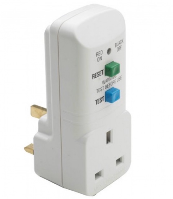
To test, I used a 300VA isolation transformer dialed down to 220Vac (China boards are rated for 220V; Malaysian grid is 230V but I am at the very end of the mains power line at a feisty 240V). For additional safety I also used a portable ELCB (RCD to Americans). Since some semiconductors (usually mains bridge rectifiers) are connected directly to mains AC sometimes there is a short from  Live to DC ground, and an ELCB will pick this up.

Portable ELCB

An isolation transformer is a two-coil transformer (ie not an autotransformer) putting out the same voltage level as its input. If the output is shorted, the current is limited by the magnetic flux saturating in its core, limiting power delivered to its VA rating. 

110Vac Isolation Transformer. Note the Earth line passes through but Live and Neutral are isolated. 


It often lets you diagnose faulty boards before it completely burns out. 60VA, or even 30VA are very handy ratings, and the idea is to progressively work up to the full device rating. I always make my own; a handy way is to use two regular (ie step-down) transformers connected back to back. To dial down the output voltage you will need to use a variable transformer to drive the isolation transformer.

2000VA Isolation transformer from Carroll & Meynell


Testing was straightforward except for one thing: the air pump continued to run despite the panel power switch being turned off. Despite having used it for a whole year, I did not really notice if it did that before. My excuse was I was struggling with tiny SMD parts. Having the air pump run meant the BT136 is on. Was the relay turning off?

Air pump relay circuit

I needed to make some live measurements. This is never a good idea when dealing with stuff connected to mains AC. The isolation transformer protects the repair item but will easily deliver a fatal shock to a human (50mA or 15VA will ruin your day, probably your life) . The mounting wires are short and the board has to be mounted vertically which means reaching past exposed live bits to probe.  

Thus far I had looked for defective parts the safe and preferred way: offline, unpowered and using a digital multimeter. If you suspected something you took it out and make some more measurements. When testing I powered up at low VA, operated the panel knobs and switches and avoided touching exposed parts. 

NPN transistor Q6 (SS8050) was an immediate suspect - with the panel switch off, its collector was 6V, way lower than the 12V if it were off. Maybe it was leaking? It tested OK dismounted: both semiconductor diode junctions seemed OK, but maybe it was partially leaking? I replaced it with a generic 2N2222 (watch it: ON Semi produces a PN2222 with reversed leads unlike my KSP2222A), but there was no change; the air pump kept running even though the panel switch is off.

An examination of the circuit provided a clue. In addition to switching in mains voltage, it also switched on 12V to Q6 (and the opamp). The capacitor C6 is 220uF and will store a walloping charge and R19_2 measures about 100K in-situ but is probably higher (the color codes are faded with heat). When switched off, it will ensured it discharged slowly into the base of Q6. The time constant is in the order of 22 seconds. And always fearing a defect I had been quick to cut off power to  the isolation transformer while testing.

Using this formula, my Change is 95% (12V to 0.6V) at time constant 22 will result in a delay time of 64.8s. I assembled and tested it again; and sure enough after a long minute the air pump went off. But why would it want do that? It is somewhat misleading to have the power on even after the panel switch is off.  The manual for a similar system yielded this clue:


Ah, that was unexpected, but at least it was not broken. I would recommend you spend that minute, set the airflow to maximum and wait for the air pump to finish doing its thing, and then turn the YX850A+ off at the power socket, for the manual goes on to say:


An auto-disconnect would be nice, maybe a few seconds after the air pump turns off. So would a thermal cutoff switch. And the triac heatsinks looked puny with the cooling fins horizontal instead of vertically where they would do most good. But that is a project for another day. 

There you have it: Hot-Air SMD Rework Station Repair.

Happy Trails.