Thursday, 26 November 2020

AS3935 Lightning Detector with I2C and ESP8266 NodeMCU ESP-12E


AS3935 Lightning Detector with I2C on ESP8266 NodeMCU ESP-12E

There are several good posts on the AS3935 with Arduino Atmel CPUs, and some with ESP8266, including code, but these tend to publish only wiring diagrams for Arduino. So, this post no big deal, really to document a working example of CJMCU AS3935 with I2C on ESP8266 NodeMCU ESP-12E.

CJMCU AS3935 Lightning Detector

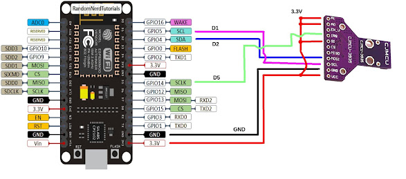
The wiring is:

AS3935                                  ESP-12E
    SCL                                    D1/GPIO5
    MISO                                  D2/GPIO4
    IRQ                                     D5/GPIO14
    VCC                                   3.3V
    GND                                   GND

In addition tie the AS3935 pins A0, A1 and SI to 3.3V

AS3935 I2C wiring for NodeMCU ESP-12E

The choice of D5 for interrupt line was guided by the excellent randomnerd reference. D3 and D4 seemed a lot more intuitive, but the ESP8266 failed to boot.

Unlike my previous posts on the AS3935, I thought it might make a change to use the one of the AS3935 libraries in the Arduino IDE database, specifically stevemarple's AS3935.h. Just navigate to 'Sketch' drop-down menu, then select 'Include Library' and then 'Manage Libraries'. 

Under 'File' and 'Preferences' you need to have the URL: http://arduino.esp8266.com/stable/package_esp8266com_index.json

The code is slightly modified from stevemarple's example to make it compile. I have uploaded a copy to github.

#include <AsyncDelay.h>
#include <SoftWire.h>
#include <AS3935.h>
#ifdef JTD
#include <DisableJTAG.h>
#endif
AS3935 as3935;
bool ledState = true;
AsyncDelay d;
ICACHE_RAM_ATTR void int2Handler(void) // 2020-11-22
{
  as3935.interruptHandler();
}

void readRegs(uint8_t start, uint8_t end)
{
  for (uint8_t reg = start; reg < end; ++reg) {
    delay(50);
    uint8_t val;
    as3935.readRegister(reg, val);
    Serial.print("Reg: 0x");
    Serial.print(reg, HEX);
    Serial.print(": 0x");
    Serial.println(val, HEX);
    Serial.flush();
  }
  Serial.print("State: ");
  Serial.println(as3935.getState(), DEC);
  Serial.println("-------------");
}
bool NoiseHigh = false;
bool Disturbed = false;
void printInterruptReason(Stream &s, uint8_t value, const char *prefix = nullptr)
{
  if (value & AS3935::intNoiseLevelTooHigh) {
    if (NoiseHigh == false) {
      if (prefix)
        s.print(prefix);
      s.println(F("Noise level too high"));
      // NoiseHigh = true;
    }  
  }
  if (value & AS3935::intDisturberDetected) {
    if (Disturbed == false) {
      if (prefix)
        s.print(prefix);
      s.println(F("Disturber detected"));
      // Disturbed = true;
    }
  }  
  if (value & AS3935::intLightningDetected) {
    if (prefix)
      s.print(prefix);
    s.println(F("Lightning detected"));
  }
}

void setup(void)
{
#ifdef JTD
  disableJTAG();
#endif
  Serial.begin(115200);
  // as3935.initialise(14, 17, 0x03, 3, true, NULL);
  as3935.initialise(4, 5, 0x03, 3, true, NULL); // 2020-11-22
  // as3935.calibrate();
  as3935.start();
  d.start(1000, AsyncDelay::MILLIS);
  while (!d.isExpired())
    as3935.process();
  Serial.println("Before setup:");
  readRegs(0, 0x09);
  // attachInterrupt(2, int2Handler, RISING); // 2 is believed to be D4, GPIO2
  attachInterrupt(14, int2Handler, RISING); // 2020-11-22 Chose D5 GPI14
  // attachInterrupt(digitalPinToInterrupt(5), int2Handler, RISING); // 2020-11-22 Chose D3 GPIO0
  d.start(1000, AsyncDelay::MILLIS);
  Serial.println("setup() done");
  readRegs(0, 0x09);
  as3935.setIndoor(true);
  as3935.setNoiseFloor(4);
  as3935.setThreshold(4);
  as3935.setSpikeRejection(0); // From AS3935_timestamp_demo.ino
  
  //as3935.calibrate();
  //Serial.println("Calibration done");
  //readRegs(0, 0x09);
  Serial.println("Masking Disturber interrupts ...");
  as3935.setRegisterBit(as3935.regInt, 5, true);
  readRegs(0, 0x09);
  pinMode(LED_BUILTIN, OUTPUT);
  digitalWrite(LED_BUILTIN, ledState);
}
uint8_t count = 0;
void loop(void)
{
  if (as3935.process()) {
    uint8_t flags = as3935.getInterruptFlags();
    uint8_t dist = as3935.getDistance();
    /*
    Serial.println("-------------------");
    Serial.println("Interrupt!");
    Serial.println("Reason(s):");
    */
    printInterruptReason(Serial, flags, "    ");
    
    if (AS3935::intLightningDetected & flags) {
      Serial.print("Distance: ");
      Serial.println(dist, DEC);
    }
  }
  if (as3935.getBusError()) {
    Serial.println("Bus error!");
    as3935.clearBusError();
  }
  // Flash the LED to show activity
  if (d.isExpired()) {
    ledState = !ledState;
    digitalWrite(LED_BUILTIN, ledState);
    // // Periodically output the AS3935 registers
    // if (++count > 5) {
    //  count = 0;
    //  readRegs(0, 0x09);
    // }
    d.start(1000, AsyncDelay::MILLIS);
  }
}


NodeMCU Base board Ver 1


I also used a baseboard V1 for my NodeMCU V3 Lua Lolin ESP-12E. Do take note of the different versions as the baseboard does not fit many of the cheap ESP-12E out there. The baseboard is just for convenience, really and you can wire the AS3935 directly to the ESP-12E. 

I was getting a little low on USB cables and had many 12V and 9V DC power supplies left over from dead TP-Link and Dlink ADSL modems. The voltage range is acceptable to the baseboard and the power jack fits. 

Have fun. I know I did. Happy Trails.

Thursday, 5 November 2020

Once more unto the breach, dear friend, once more ... APC Back-UPS RS1000 Repair


APC Back-UPS RS1000

I first encountered it 13 years ago, in 2008. Even then it was past its prime, bought at a private auction for peanuts. It started up, then indicated 'overload' and shut down. Back then I needed to learn about UPS and the RS1000 was a nice roomy design and a large PCB which seemed easy to work with.

Main PCB: top of picture is front of UPS. Charging section is on the bottom left corner


You took out the screws and lifted the front cover from the middle in 2 sections. The bottom half covered the battery compartment. The top front flap had to be pried off together with the right side cover, and comes off with a nasty crack. Once exposed it was easy to reconnect the sections for testing.

Important: Do Not Attempt this Repair unless you are qualified. Not only there are hazardous voltages inside, it will continue to be hazardous if the UPS is disconnected from the mains. In additional since there are switch-mode power modules inside, connecting an oscilloscope to it will result in damage, fire or death.

It sat in my study for 2 months before I found the fault: there were two shorted MOSFETS, Q1 and Q2, IRF740. Replaced that plus a blown fuse and it worked again. I had a good guess at the root cause: there were signs a gecko used to live there. The nice roomy UPS must have been a good place for a gecko to keep warm.

Typical Malaysian house gecko 


It was some 9 years, in 2015 before it was brought in for repair again.  It started up, indicated 'overload' and shut down. Call me simple, but I went straight to the battery charging circuit. This time a deceased and mummified gecko was still in there. 


Bad Neighborhood: An IoT Power Extension used for lamps has a lot going for a gecko: lots of insects attracted to the light. It is warm, dry and safe from kingfishers, rats and other predators.  There is just one problem ... electrocution


Again two shorted IRF740s, this time Q1 and Q3. The PCB was getting a little beat up with the second rework, but it started up nicely.

It was a little quick to switch over to battery operation, but you could decrease the sensitivity by turning it off, then holding the button down until all 3 lights lit up. Then you pressed the button again to select: one light for minimum sensitivity. 

And back it goes into service. It came back 5 years later, about 4 months ago this year. This time there was nothing wrong, and everything wrong: the owner did not need it anymore. Desktop computers are now notebooks with 3 hour or more battery life and there is little use for a UPS with a backup time of 15 minutes.

For four months it backed up my npm server, a laptop. During one long power outtage, it got quite hot and right after that would not go back to 'online' mode even after the power came back. There is AC power in its non-battery-backed power sockets, and it charged the batteries when it is shut down. But when it is started up, it tests the batteries, then the mains voltage, and switches to battery operation. 

Perhaps after a few years its 'Line Sense' circuit had deteriorated. Maybe a gecko had set up shop in it again. My first thought was to throw it out: there was little use for it. But then a half-hearted google search turned up the full schematics for it!

Well maybe one last hurrah. If I moved my npm server to a raspberry pi 3, it should be able to run on battery for 2 hours or more.


So off with the cover. This time there was no gecko. Just the 'Line Sense' problem. The components are surface-mount but just about large enough to handle without an airgun.

The first opamp in IC8 (LM358) is a difference amplifier. It reads the incoming mains AC directly, using 2M series resistors to step down 325V (230Vac nominal is 325 Vpeak) to around 3V.


Line Sense (IC8). CPU is at top center.


The second opamp is (I think) a precision half-wave rectifier which is read directly by the CPU analog input. The 'Sync Circuit' output is connected to the CPU digital input, probably used to sense zero crossings for a smooth switchover.

When I measured the resistance of the resistors, diodes and opamps (with power off and circuit discharged!) they seems OK, nothing short or open-circuited. Next would be a power test. Plugging in the battery alone did not produce power at the LM358.

But plugging in the AC mains (with the UPS still shut down) did. 12V supply came up. But the negative rail '-8V' seemed a little low at -4.2V. Now the AC mains Live is connected to the opamp inverting input, and it can only go as negative as its voltage rail. The precision rectifier will rectify it to the correct polarity for the CPU analog input. If the negative rail is not low enough, the Live voltage sensed will correspondingly drop. This seems to square with the observed fault.

So we go on to the -8V power schematic.


Maybe the designer is old-school, but this is a flying-capacitor charge pump, straight out of the textbooks. Most of the kids would have dropped in a cheap surface-mount DC-DC IC. The CPU digital output line 'pumps'  CHRG_PUMP_OSC at a fixed frequency. This provides 12V on an off to the 'flying' capacitor C40 which charges up to 12V via Q25.

C20 is prevented from discharging by the diodes D21. Their polarities ensure that the output is negative, which allowing for diode forward drops and Q25's Vce, -8V seems a reasonable final output.

But what could be wrong?  There is some output, just a little low at -4.2V. Q25 or Q26 could be defective. It could be D19 shorting or D21 leaking. But the most likely is C41 and C40 has lost most of their charge. Electrolytic capacitors contain electrolyte, and is likely to dry out. They have a shelf life of 6 months before they are out of spec. And it has been, what, 12 years?

Again, with power off and battery disconnected and the PCB allowed to discharge, diode-tested the diodes and transistors (a bipolar transistor is simply 2 diodes stacked up). They seemed OK. This leaves the capacitors.

220uF test capacitor soldered across C41. 
 

To test the capacitors C40 and C41 it seemed easiest to simply parallel a new capacitor across the old one. In fact just adding one capacitor should improve the resulting output power. If possible, over-size the rating (I used 220uF) a little as the old one will act more as a load. I simply soldered it across C41.

On connecting the battery and mains voltage the voltage went up to -5.8V. And even better, when the UPS was started up, it tested the battery, then switched to 'online' mode!

For final repair, I ordered some surface-mount 22uF capacitors. There is nothing wrong with my 'test' capacitor, but the capacitor is heavy and lies horizontally when the RS1000 is upright and as a result may work itself loose after a few years.

[2020-11-10 update]: With new (Panasonic EEEHD1C220AR) SMD 16V 22uF electrolytic capacitors for C40 and C41, the negative rail "-8V" now measures -9.2V. Element14 is not the cheapest, but they hold local stock and I really did not want to wait 4 weeks with the UPS innards scattered over the work table.

So, it is "once more into the breach, dear friend". It's better to soldier on. Better the line of fire than the storage shelf.

Happy Trails. 

"How dull it is to pause, to make an end, To rust unburnish'd, not to shine in use!" - Tennyson, 'Ulysses'