Friday, 23 March 2018

Debugging the ESP8266 ESP-01S Relay Module

ESP8266 ESP-01S Relay Module Relay WIFI Smart Socket with ESP-01S

In a previous post I wrote about switching a 5V relay module using the ESP-12E over WiFi. Well just two days ago I spotted this delicious module for just RM26.90. It arrived today- hurrah for Internet commerce!

I powered on - and nothing happened. The red power light on the ESP-01S came on as usual, but there is none of the familiar blue flash on startup.


A little check with a multi-meter revealed that GPIO0 and CH_PD were not at the high (ie 3.3V) voltage level required for startup. A quick search on the Internet unearthed a schematic which confirmed this:

The relay module schematic has no provision for GIO0 and CH_PD tied high

The modification is easy enough - I tied GPIO0 high to 3.3V,via a 10K resistor. CH_PD I tied directly to 5V, not ideal, so you are encouraged to use a resistor there as well.


Modifications to GPIO0 and CH_PD

And that was all it took- it powered on quite happily (I used a modified version of the Arduino IDE Blink sketch.

Working ESP-01S relay module
Here is a Youtube video of it clicking away ... Happy Trails.

Wednesday, 21 March 2018

Programming the ESP8266 ESP-01 with Arduino IDE

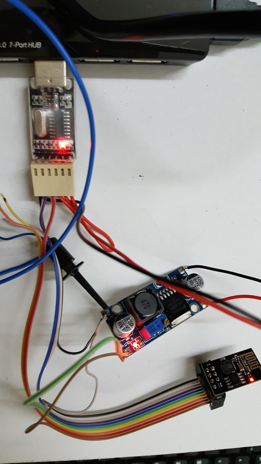
CH340 USB to serial TTL dongle, LM2596 buck converter and the ESP-01
Julian Hartline has an excellent post on this.

My ESP-01 from JFR Technologies turned out to be a rather ancient one - which probably explains the low price.

I used this CH340G serial TTL dongle, which also put out a 5V pin. This I used to power the ESP-01 via an LM2596 buck converter.

The main problem was with the 5V power into this whole assembly. The power required to program the ESP-01 is more than that of simply getting it to run. I had to plug it directly into my 3A externally powered USB 3.0 hub.  If I used a USB extension or a USB volt/current meter it would run up but fail to program.

Lastly it is worth repeating:
1. Select the 'Tools->Board->Generic ESP8266 Module' option in Arduino IDE
2. Set the upload speed to 9600 (most newer ESO-01 use 115200. My ESP-01 was 115200 during normal run but 9600 during program upload
2. Pull down GPIO0
3. Reset the ESP-01 by pulling down RST then releasing. The blue blinkenlight should flash.
4. Launch the upload 'Sketch->Upload'

Happy Trails.

Tuesday, 20 March 2018

IoT Relay/Switch using the ESP8266 NodeMCU ESP-12E Lua V3 and Arduino IDE

IoT Switch: From top: 5V relay PCB, Level Translator PCB and ESP-12E
As mentioned in an earlier post, lighting up a LED is very similar to controlling a relay. In place of the relay, we use a relay PCB with an optically-isolated input. I bought mine for RM9.99 from here.

5V opto-isolated Relay PCB
Since the ESP8266 ESP-12E is a 5V device, we need to translate its output to 5V. I am usually inclined to use a 1.8V zener diode like the TZS4678-GS08, costing some RM1.14. However an Arduino-type 4-channel  level converter is only RM1.35.

4-Channel Logic Level Converter
Unlike the resistor network or the zener diode method, this is an active circuit and uses the MOSFET BSS138:


There is a full explanation on the schematic here.

The wiring is quite straightforward:

ESP-12E    Level Converter   2-Channel Relay
3.3V           LV             HV        5V
GND          GND         GND      GND
D6              LV1           HV1      IN1
D7              LV2           HV2      IN2

Top wiring to ESP-12E, bottom wiring to 5V Relay PCB
The program, a Lua 'sketch' for the Arduino IDE, is much the same as the last post, tweaked a little to add a second channel. The only fiddle here is if we used D5, it seems to interfere with the programming of the ESP-12E via its USB serial port. If you do use D5, simply disconnect the level translator from the ESP-12E before you program it.

/*
 *  This sketch demonstrates how to set up a simple HTTP-like server.
 *  The server will set a GPIO pin depending on the request
 *    http://server_ip:8080/gpio/0 will set the GPIO2 low,
 *    http://server_ip:8080/gpio/1 will set the GPIO2 high
 *  server_ip is the IP address of the ESP8266 module, will be
 *  printed to Serial when the module is connected.

static const uint8_t D0 = 16;
static const uint8_t D1 = 5;
static const uint8_t D2 = 4;
static const uint8_t D3 = 0;
static const uint8_t D4 = 2;
static const uint8_t D5 = 14;
static const uint8_t D6 = 12;
static const uint8_t D7 = 13;
static const uint8_t D8 = 15;
static const uint8_t D9 = 3;
static const uint8_t D10 = 1;
*/


#include <ESP8266WiFi.h>

const char* ssid = "YourAcessPoint";
const char* password = "YourSecretPassword";

// Create an instance of the server
// specify the port to listen on as an argument
WiFiServer server(8080);

void setup() {
  Serial.begin(115200);
  delay(10);

  // prepare GPIO
  pinMode(D6, OUTPUT);
  pinMode(D7, OUTPUT);
  digitalWrite(D6, HIGH);
  digitalWrite(D7, HIGH);
  Serial.println("Relays off");

  // Connect to WiFi network
  Serial.println();
  Serial.print("Connecting to ");
  Serial.println(ssid);

  WiFi.mode(WIFI_STA);
  WiFi.begin(ssid, password);

  while (WiFi.status() != WL_CONNECTED) {
    delay(500);
    Serial.print(".");
  }
  Serial.println("");
  Serial.println("WiFi connected");

  // Start the server
  server.begin();
  Serial.println("Server started");

  // Print the IP address
  Serial.println(WiFi.localIP());
}

int val = 1;
int val2 = 1;

void loop() {
  // Check if a client has connected
  WiFiClient client = server.available();
  if (!client) {
    return;
  }

  // Wait until the client sends some data
  Serial.println("new client");
  while(!client.available()){
    delay(1);
  }

  // Read the first line of the request
  String req = client.readStringUntil('\r');
  Serial.println(req);
  client.flush();

  // Match the request
  String s = "";
  // Prepare the response
  Serial.print("Input string is ");
  Serial.println(req);
  if (req.indexOf("/D6/0") != -1) {
    val = 0;
    s = "HTTP/1.1 200 OK\r\nContent-Type: text/html\r\n\r\n<!DOCTYPE HTML>\r\n<html>\r\nD6 is now ";
    s += (val)?"high":"low";
    s += "</html>\n";
  }
  else if (req.indexOf("/D6/1") != -1) {
    val = 1;
    s = "HTTP/1.1 200 OK\r\nContent-Type: text/html\r\n\r\n<!DOCTYPE HTML>\r\n<html>\r\nD6 is now ";
    s += (val)?"high":"low";
    s += "</html>\n";
  }
  else if (req.indexOf("/D7/0") != -1) {
    val2 = 0;
    s = "HTTP/1.1 200 OK\r\nContent-Type: text/html\r\n\r\n<!DOCTYPE HTML>\r\n<html>\r\nD7 is now ";
    s += (val2)?"high":"low";
    s += "</html>\n";
  }
  else if (req.indexOf("/D7/1") != -1) {
    val2 = 1;
    s = "HTTP/1.1 200 OK\r\nContent-Type: text/html\r\n\r\n<!DOCTYPE HTML>\r\n<html>\r\nD7 is now ";
    s += (val2)?"high":"low";
    s += "</html>\n";
  }
  else if (req.indexOf("/index.html") != -1) {
    s = "HTTP/1.1 200 OK\r\nContent-Type: text/html\r\n\r\n<!DOCTYPE HTML>\r\n<html>\r\nHello, world.</html>\n";
  }
  else if (req.indexOf("/favicon.ico") != -1) {
    Serial.println("End of command");
    client.stop();
  }

  else {
    s = "HTTP/1.1 200 OK\r\nContent-Type: text/html\r\n\r\n<!DOCTYPE HTML>\r\n<html>\r\nInvalid request: ";
    s += req;
    s += "</html>\n";
    Serial.println("invalid request");
    Serial.println(req);
    client.print(s);
    delay(10);
    client.stop();
    return;
  }

  // Set GPIO2 according to the request
  if (val == 0)
    digitalWrite(D6, LOW);
  if (val == 1)
    digitalWrite(D6, HIGH);
  if (val2 == 0)
    digitalWrite(D7, LOW);
  if (val2 == 1)
    digitalWrite(D7, HIGH);

  client.flush();

  // Send the response to the client
  client.print(s);
  delay(1);
  Serial.println("Client disonnected");

  // The client will actually be disconnected
  // when the function returns and 'client' object is destroyed
}

As before, you turn on the first relay using:
http://yourIPaddress/D6/0

And off using:
http://yourIPaddress/D6/1

The commands for the second relay are:
http://yourIPaddress/D7/0
http://yourIPaddress/D7/1

The total cost of the parts was something like RM21.90 + RM9.99 + RM1.35 or RM33.24, not counting the 5V power supply and  the various bits of wires and connectors.

This is very similar to the Sonoff ITEAD IoT switch which sells for only RM30.84:

Sonoff ITEAD
There you have it: your DIY IoT switch actually sets you back some RM2.40. But as we shall see later, the Sonoff, among others, has some serious security problems, like the Krack exploit. Rolling our own IoT relay switch is the first step to taking control of our IoT security, rather than relying on the vendors' updates, both of the firmware and the accompanying app.

You can actually upgrade the Sonoff firmware yourself. Happy trails.  

Saturday, 10 March 2018

SPI Master & Slave Programs with the ESP8266 NodeMCU ESP-12E Lua V3 and Arduino IDE

ESP-12E as SPI Master (top) and SPI Slave (bottom)
After learning how to program the ESP8266 using the Arduino IDE, I thought it might be a good idea to interface the ESP8266 with Arduino-family devices. There are plenty of articles in the Web on interfacing the ESP8266 with Arduino CPUs like the Uno but comparatively few on interfacing to Arduino non-CPU PCBs.

PCBs like this relay boards are easy to interface to; you use the same method as the blinking LED sketch in my last post.
This 5V Arduino relay module costs as little as RM5

But other PCBs like this MAX7219 LED 7-segment Display costs a mere RM9.60 and uses the SPI or Serial Peripheral Interface:

MAX7219 LED 7-segment display module
 Quite a few PCBs use the I2C interface, including this delicious RM5.90 realtime clock:

PCF8563T Realtime Clock

SPI involves a master device and a slave device. I used an ESP-12E for both. The master code from the Arduino IDE "Examples->SPISlave->SPISlave_SafeMaster" menu works and is reproduced here as the code tends to change from version to version:

/*
    SPI Safe Master Demo Sketch
    Connect the SPI Master device to the following pins on the esp8266:

    GPIO    NodeMCU   Name  |   Uno
   ===================================
     15       D8       SS   |   D10
     13       D7      MOSI  |   D11
     12       D6      MISO  |   D12
     14       D5      SCK   |   D13

    Note: If the ESP is booting at a moment when the SPI Master has the Select line HIGH (deselected)
    the ESP8266 WILL FAIL to boot!
    This sketch tries to go around this issue by only pulsing the Slave Select line to reset the command
    and keeping the line LOW all other time.

*/
#include <SPI.h>

class ESPSafeMaster
{
private:
    uint8_t _ss_pin;
    void _pulseSS()
    {
        digitalWrite(_ss_pin, HIGH);
        delayMicroseconds(5);
        digitalWrite(_ss_pin, LOW);
    }
public:
    ESPSafeMaster(uint8_t pin):_ss_pin(pin) {}
    void begin()
    {
        pinMode(_ss_pin, OUTPUT);
        _pulseSS();
    }

    uint32_t readStatus()
    {
        _pulseSS();
        SPI.transfer(0x04);
        uint32_t status = (SPI.transfer(0) | ((uint32_t)(SPI.transfer(0)) << 8) | ((uint32_t)(SPI.transfer(0)) << 16) | ((uint32_t)(SPI.transfer(0)) << 24));
        _pulseSS();
        return status;
    }

    void writeStatus(uint32_t status)
    {
        _pulseSS();
        SPI.transfer(0x01);
        SPI.transfer(status & 0xFF);
        SPI.transfer((status >> 8) & 0xFF);
        SPI.transfer((status >> 16) & 0xFF);
        SPI.transfer((status >> 24) & 0xFF);
        _pulseSS();
    }

    void readData(uint8_t * data)
    {
        _pulseSS();
        SPI.transfer(0x03);
        SPI.transfer(0x00);
        for(uint8_t i=0; i<32; i++) {
            data[i] = SPI.transfer(0);
        }
        _pulseSS();
    }

    void writeData(uint8_t * data, size_t len)
    {
        uint8_t i=0;
        _pulseSS();
        SPI.transfer(0x02);
        SPI.transfer(0x00);
        while(len-- && i < 32) {
            SPI.transfer(data[i++]);
        }
        while(i++ < 32) {
            SPI.transfer(0);
        }
        _pulseSS();
    }

    String readData()
    {
        char data[33];
        data[32] = 0;
        readData((uint8_t *)data);
        return String(data);
    }

    void writeData(const char * data)
    {
        writeData((uint8_t *)data, strlen(data));
    }
};

ESPSafeMaster esp(SS);

void send(const char * message)
{
    Serial.print("Master: ");
    Serial.println(message);
    esp.writeData(message);
    delay(10);
    Serial.print("Slave: ");
    Serial.println(esp.readData());
    Serial.println();
}

void setup()
{
    Serial.begin(115200);
    SPI.begin();
    esp.begin();
    delay(1000);
    send("Hello Slave!");
}

void loop()
{
    delay(1000);
    send("Are you alive?");
}

Unfortunately the "Examples->SPISlave->SPISlave_Test" did not work for me. The Slave could read the master but its reply seems corrupted. Luckily I found a working version in the ESP8266 Community Forum:

/*
    SPI Slave Demo Sketch
    Connect the SPI Master device to the following pins on the esp8266:

    GPIO    NodeMCU   Name  |   Uno
  ===================================
     15       D8       SS   |   D10
     13       D7      MOSI  |   D11
     12       D6      MISO  |   D12
     14       D5      SCK   |   D13

    Note: If the ESP is booting at a moment when the SPI Master has the Select li
ne HIGH (deselected)
    the ESP8266 WILL FAIL to boot!
    See SPISlave_SafeMaster example for possible workaround

*/

#include "SPISlave.h"

void setup()
{
    Serial.begin(115200);
    Serial.setDebugOutput(true);
    Serial.println();

    // data has been received from the master. Beware that len is always 32
    // and the buffer is autofilled with zeroes if data is less than 32 bytes long
    // It's up to the user to implement protocol for handling data length
    SPISlave.onData([](uint8_t * data, size_t len) {
        String message = String((char *)data);
        char answer[33];
        if(message.equals("Hello Slave!")) {
            strcpy(answer, "Hello Master!");
        } else if(message.equals("Are you alive?")) {
            sprintf(answer, "Alive for %u seconds!", millis() / 1000);
        } else {
            strcpy(answer, "Say what?");
        }
        SPISlave.setData(answer);
        Serial.printf("Question: %s\Answer: %s\n", (char *)data, answer);
    });

    // The master has read out outgoing data buffer
    // that buffer can be set with SPISlave.setData
    SPISlave.onDataSent([]() {
        Serial.println("Answer Sent");
    });

    // status has been received from the master.
    // The status register is a special register that bot the slave and the master can write to and read from.
    // Can be used to exchange small data or status information
    SPISlave.onStatus([](uint32_t data) {
        Serial.printf("Status: %u\n", data);
        SPISlave.setStatus(millis()); //set next status
    });

    // The master has read the status register
    SPISlave.onStatusSent([]() {
        Serial.println("Status Sent");
    });

    // Setup SPI Slave registers and pins
    SPISlave.begin();

    // Additional setting to have MISO change on falling edge
    SPI1C2 |= 1 << SPIC2MISODM_S;

    // Set the status register (if the master reads it, it will read this value)
    SPISlave.setStatus(millis());

    // Sets the data registers. Limited to 32 bytes at a time.
    // SPISlave.setData(uint8_t * data, size_t len); is also available with the same limitation
    SPISlave.setData("Ask me a question!");
}

void loop() {}

The two ESP-12E, master and slave are wired thus:

As per the comments in the two sketches, the ESP-12E pin assignments are:

                  Master               Slave
              D8       SS      -   SS          D8
              D7      MOSI  -   MOSI    D7
              D6      MISO  -   MISO    D6
              D5      SCK    -   SCK      D5

I plugged both into the same laptop, and the slave came up as /dev/ttyUSB0 and the master /dev/ttyUSB1. By clicking on "Tools->Port" I could switch between the two serial ports and program the master and slave in turn.

When working correctly you should get the following output from the Master's Serial Monitor:

Master: Are you alive?
Slave: Alive for 44 seconds!

Master: Are you alive?
Slave: Alive for 45 seconds!

Master: Are you alive?
Slave: Alive for 46 seconds!

Master: Are you alive?
Slave: Alive for 47 seconds!

Master: Are you alive?
Slave: Alive for 48 seconds!

Now if you flipped over to /dev/ttyUSB0 and relaunched the Serial Monitor, you should get:

Question: Are you alive?Answer: Alive for 44 seconds!
Answer Sent
Question: Are you alive?Answer: Alive for 45 seconds!
Answer Sent
Question: Are you alive?Answer: Alive for 46 seconds!
Answer Sent
Question: Are you alive?Answer: Alive for 47 seconds!
Answer Sent

There you have it, SPI communication using the ESP8266 and Arduino IDE. 

Happy Trails.
 

Tuesday, 27 February 2018

Programming the ESP8266 NodeMCU ESP-12E Lua V3 with Arduino IDE

ESP-12E running the sample LED Blink Lua script 
In my last post I tested the ESP8266-based ESP-12E using its partially-available AT Command set, and showed that we can make a simple IoT device with it.

Alternatively we can directly program the 80MHz 32-bit Tensilica CPU inside the ESP8266. After all, the  NodeMCU folks wrote ESP8266 firmware so that we can run Lua programs directly on the ESP8266.

If you are new to all this, don't be fazed- all this new stuff is really easy to learn and use. They are designed like that. This is also my first experience of NodeMCU, Lua and ESP8266.

We program the ESP-12E using the Arduino IDE. It supports much more than the ESP8266, which is just a tiny part of the Arduino ecosystem.
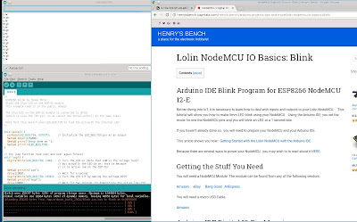
Screenshot of Arduino IDE on Slackware 14.2 (bottom left). and the Arduino IDE Serial Port Monitor (top left). Henry's Bench website (right)

I would have preferred a smaller program, the command line-based nodemcu-uploader would have been perfect, but it was unable to work with my ESP-12E. I suspect I would first have to change the firmware.

Since I am running Linux Slackware 14.2, we first need to install Arduino IDE. I got the source files arduino-1.8.5-linux64.tar.xz from here.  Using my root account, I simply ran the install script:
$./install.sh

Still as root (otherwise you need to give yourself the permissions to access the USB device /dev/ttyUSB0), and still using the same directory you unpacked your source files:

$arduino-1.8.5/arduino

Henry's Bench does a great job explaining how to set up Arduino IDE for the ESP8266. I would just add that you need a working Internet connection to get it done. His sample program, which I copied and pasted into my Arduino IDE worked right out of the box.

To program and run the stock sample Blink sketch (Lua programs are called sketches), again please refer to the excellent example in Henry's Bench.

While you are setting up the LED circuit, it is sometimes helpful to have an idea how the Blink program is running. I have modified the Blink sketch slightly so that it outputs messages to the Arduino Serial Monitor as well:

void setup() {
  pinMode(LED_BUILTIN, OUTPUT);     // Initialize the LED_BUILTIN pin as an output
  Serial.begin(115200);
  Serial.print("Setup done on ");
  Serial.println(LED_BUILTIN);
}

// the loop function runs over and over again forever
void loop() {
  digitalWrite(LED_BUILTIN, LOW);   // Turn the LED on (Note that LOW is the voltage level
                                    // but actually the LED is on; this is because
                                    // it is active low on the ESP-01)
  Serial.println("Low");                                
  delay(1000);                      // Wait for a second
  digitalWrite(LED_BUILTIN, HIGH);  // Turn the LED off by making the voltage HIGH
  Serial.println("High");
  delay(2000);                      // Wait for two seconds (to demonstrate the active low LED)
}

Rather than going to the trouble of building another 3.3V power module for this test, I have simply directly connected the LED to pin D0 of the ESP-12E. The circuit in Henry's Corner is a much better one; it results in a bright light and will work reliably without over-stressing the ESP8266's GPIO output pin.

Often modern CPUs have short-circuit protection for their IO pins, and often the output pins are strong enough to light up an LED dimly. It helps to chose a red LED (they are the oldest and most efficient). Luckily, in this case I got away with it; the LED was just bright enough to be seen, although I had to turn off my study lights for it to come out in the photo.

One possible pitfall with this method is the LED will take up precious mA of power from your ESP-12E PCB. The ESP8266 is effifcient enough but it seems to have trouble powering up from many laptops' USB ports and most USB hubs.

I am powering my ESP-12E from a D-Link USB 3.0 hub with 4A of external power. If your system gets all flakey, you are probably better off using the method in Henry's Bench. The current draw of the ESP-12E is normally about 60mA. When the LED turns on this increased to 80mA. This means the ESP8266 IC is putting out 20mA to the LED which is very close to its maximum running current.

The Blink sketch LED circuit from Henry's Corner


You now have an ESP8266 running a native (ie stored onboard) Lua program on NodeMCU firmware. If you now exit from Arduino IDE, the ESP-12E program should continue to run on its own. In fact the program will now start up every time you turn the device on.

ESP8266 as IoT Digital Output controlling an LED 


Next to make it an IoT application, navigate thus:

File->Examples->ESP8266->ESP8266WiFi->WiFiWebServer

to the sketch WiFiWebServer.

/*
 *  This sketch demonstrates how to set up a simple HTTP-like server.
 *  The server will set a GPIO pin depending on the request
 *    http://server_ip/gpio/0 will set the GPIO2 low,
 *    http://server_ip/gpio/1 will set the GPIO2 high
 *  server_ip is the IP address of the ESP8266 module, will be
 *  printed to Serial when the module is connected.
 */

#include <ESP8266WiFi.h>

const char* ssid = "your-ssid";
const char* password = "your-password";

// Create an instance of the server
// specify the port to listen on as an argument
WiFiServer server(80);

void setup() {
  Serial.begin(115200);
  delay(10);

  // prepare GPIO2
  pinMode(16, OUTPUT);
  digitalWrite(16, 0);

  // Connect to WiFi network
  Serial.println();
  Serial.println();
  Serial.print("Connecting to ");
  Serial.println(ssid);

  WiFi.mode(WIFI_STA);
  WiFi.begin(ssid, password);

  while (WiFi.status() != WL_CONNECTED) {
    delay(500);
    Serial.print(".");
  }
  Serial.println("");
  Serial.println("WiFi connected");

  // Start the server
  server.begin();
  Serial.println("Server started");

  // Print the IP address
  Serial.println(WiFi.localIP());
}

void loop() {
  // Check if a client has connected
  WiFiClient client = server.available();
  if (!client) {
    return;
  }

  // Wait until the client sends some data
  Serial.println("new client");
  while(!client.available()){
    delay(1);
  }

  // Read the first line of the request
  String req = client.readStringUntil('\r');
  Serial.println(req);
  client.flush();

  // Match the request
  int val;
  if (req.indexOf("/gpio/0") != -1)
    val = 0;
  else if (req.indexOf("/gpio/1") != -1)
    val = 1;
  else {
    Serial.println("invalid request");
    client.stop();
    return;
  }

  // Set GPIO2 according to the request
  digitalWrite(16, val);

  client.flush();

  // Prepare the response
  String s = "HTTP/1.1 200 OK\r\nContent-Type: text/html\r\n\r\n<!DOCTYPE HTML>\r\n<html>\r\nGPIO is now ";
  s += (val)?"high":"low";
  s += "</html>\n";

  // Send the response to the client
  client.print(s);
  delay(1);
  Serial.println("Client disonnected");

  // The client will actually be disconnected
  // when the function returns and 'client' object is detroyed
}

I have simple changed the GPIO pin to the D0 pin I connected my LED to:

  // prepare GPIO2
  pinMode(16, OUTPUT);
  digitalWrite(16, 0);

And further down, near the bottom:
  // Set GPIO2 according to the request
  digitalWrite(16, val);

Compile and upload the sketch to the ESP-12E. Over at a convenient browser in your phone, laptop or desktop type out:

http://IPaddress:8080/gpio/1

And the LED turns on, as before. You might notice I use the webserver port 8080, whereas the normal port to use is 80. This is because my website www.cmheong.com is already using port 80, and I reconfigured my modem router to map port 8080 in the browser to port 80 in the ESP-12E.

There you have it: a simple IoT control of an LED. Add a cheap Arduino relay PCB, and you should be able to switch useful things like light bulbs.

Until the next post then, Happy Trails.

Sunday, 25 February 2018

Internet of Things (IoT) for just RM21.90: the ESP8266 NodeMCU ESP-12E Lua V3

ESP-12E. Reset button is at the top left.
When I finished the last post on the ESP8266, I bought an ESP-12E from robotedu.my for just RM21.90, and it arrived the day after! How could I resist the new toy?

Communication should be simple. There is a CH340G USB to serial converter IC on the ESP-12E and a micro USB connector to boot, so I plugged it into my laptop. True enough a new device file came up: /dev/ttyUSB0. No surprises there.

I ran minicom, and this time it failed with 'Device /dev/ttyUSB0 is locked'. Started up minicom without resetting the device with
minicom -o

The ESP-12E was not responsive. Now there is a reset button on it and every time it was pressed the blue led flashed, and minicom detected something. Eventually, by trying the baud rates one by one, at 115200 baud I got part of a message when it was reset: 'ready'. Well and good, but it refused to go any further. 

So it is not going to be simple. A few weeks later, I tried again. This time by first searching the web for startup problems with this board. This link mentioned the board was a little prone to power problems.

Luckily, by this time, yet another new toy had arrived, the D-Link DUB-1370 USB 3.0 Hub, which came with a stonking 4A 5V external power supply. Time to upgrade the ESP-12E's power supply.


This time minicom had no trouble with the device file (/dev/ttyUSB0). The PCB has 'use 9600bps' helpfully printed on it, but it did not work. Luckily I noticed the Reset button, marked 'RST'. On pressing it there are a couple of satisfying flashes from a blue blinkenlight.

A search of WiFi access points came up with a new one:

          Cell 03 - Address: 2E:3A:E8:42:C1:55
                    Channel:1
                    Frequency:2.412 GHz (Channel 1)
                    Quality=70/70  Signal level=-20 dBm
                    Encryption key:off
                    ESSID:"ESP_42C155"
                    Bit Rates:5.5 Mb/s; 11 Mb/s; 1 Mb/s; 2 Mb/s; 6 Mb/s
                              12 Mb/s; 24 Mb/s; 48 Mb/s
                    Bit Rates:54 Mb/s; 9 Mb/s; 18 Mb/s; 36 Mb/s
                    Mode:Master
                    Extra:tsf=0000000054adf21d
                    Extra: Last beacon: 5750ms ago
                    IE: Unknown: 000A4553505F343243313535
                    IE: Unknown: 01088B9682840C183060
                    IE: Unknown: 030101
                    IE: Unknown: 32046C122448
                    IE: Unknown: DD0918FE34030100000000

So there are some signs of life. An Internet search for ESP_42C155 turned up nothing. But luckily the reset button produced some rubbish characters. I simply kept changing the serial port (/dev/USB0)'s baud rate until the output made sense on reset. Eventually, it produced 'ready' at 115200 baud, 8-bit, 1-stop and no parity.

Aha. Trying the tested command sequence (see my past post)

AT

followed by Ctrl-M and Ctrl-J. And got a very satisfying output:
AT

OK

It was time to look in the manual. This produced the version numbers:

AT+GMR
AT version:1.1.0.0(May 11 2016 18:09:56)
SDK version:1.5.4(baaeaebb)
compile time:May 20 2016 15:08:19
OK

Now since the Access Point ESP_42C155 was not encrypted, I logged my laptop into it. dhclient ran successfully and assigned the IP address of 192.168.4.2 to my laptop:

$dhclient -v -1 wlan0
Internet Systems Consortium DHCP Client 4.3.4
Copyright 2004-2016 Internet Systems Consortium.
All rights reserved.
For info, please visit https://www.isc.org/software/dhcp/

Listening on LPF/wlan0/54:27:1e:50:38:c7
Sending on   LPF/wlan0/54:27:1e:50:38:c7
Sending on   Socket/fallback
DHCPDISCOVER on wlan0 to 255.255.255.255 port 67 interval 8
DHCPREQUEST on wlan0 to 255.255.255.255 port 67
DHCPOFFER from 192.168.4.1
DHCPACK from 192.168.4.1
bound to 192.168.4.2 -- renewal in 2863 seconds

So the little PCB not only has an Access Point, but has a DHCP server. Many of the AT commands in the manual did not work, but a good many did. There are probably a lot of variations in the NodeMCU firmware. This AT command confirms the DHCP server:

AT+CWDHCP?
+CWDHCP:3
OK

And I can even ping my laptop:
AT+PING="192.168.4.2"
+1

OK

However trying the link http://192.168.4.1 from a browser failed. Some posts had suggested some ESP-12E boards also had a webserver. Just not this one.

No matter. Now an IoT device needs to be able to connect to the Internet. I set the ESP-12E to be a WiFi client as well as an Access Point:

AT+CWMODE=3

OK

And set it to log into my house WiFi Access Point:

AT+CWJAP="HouseAP","password"
WIFI CONNECTED
WIFI GOT IP

OK

AT+CIFSR
+CIFSR:APIP,"192.168.4.1"
+CIFSR:APMAC,"2e:3a:e8:42:c1:55"
+CIFSR:STAIP,"172.16.1.102"
+CIFSR:STAMAC,"2c:3a:e8:42:c1:55"

OK

Cool. It looks like the house AP has assigned it an IP. To confirm Internet access I pinged the Google nameserver 8.8.8.8:

AT+PING="8.8.8.8"
+38

OK

This looks good. The manual mentions the ESP-12E can be made to communicate with a WeChat App (the China version of WhatsApp). It can also be upgraded from the Internet. But to keep this blog post short, we go with the AT command manual for now.

An IoT device also needs to be able to receive commands from my phone or laptop. The ESP-12E not having a webserver or ssh server running, perhaps we can try a raw network socket. From the manual, we first dip a toe in the water:

AT+CIPSTART=?
+CIPSTART:(id)("type"),("ip address"),(port)
+CIPSTART:((id)"type"),("domain name"),(port)

OK

That looked good, so let's try to connect to an arbitrary network socket 3344 on the laptop. We can use TCP/IP but let's try the socket raw, using UDP:

AT+CIPSTART="UDP","192.168.4.2",3344
CONNECT

OK

A quick check shows the connection is good:

AT+CIPSTATUS
STATUS:4
+CIPSTATUS:0,"UDP","192.168.4.2",3344,43972,0

OK

Over at the laptop I ran a bash command nc to read the port:

$nc -ul -p 3344

Back at the minicom terminal, I issue:

AT+CIPSEND=11

OK
>

This looks good. The string 'Hello world' is exactly 11 characters, and on typing it into minicom, over at the laptop I get:

$nc -ul -p 3344
Hello world

So we have the basic elements of an IoT device. It can send messages to my laptop, albeit with much typing (in particular the use of uppercase AT commands terminated with Ctrl-M Ctrl-J made things quite ponderous. This can be automated from the laptop using a python script:

$python
Python 2.7.11 (default, Mar  3 2016, 13:35:30)
[GCC 5.3.0] on linux2
Type "help", "copyright", "credits" or "license" for more information.
>>> import serial
>>> port=serial.Serial('/dev/ttyUSB0', 115200, timeout=3)
>>> port.write('AT\r\n');port.read(100)
4
'\r\nOK\r\nAT\r\r\n\r\nOK\r\n'
>>> port.write('Hello world');port.flush();port.read(100)
11
'\r\nRecv 11 bytes\r\n\r\nSEND OK\r\n'
>>>

Much work remains. The GPIO commands like AT+SYSGPIOREAD and AT+SYSGPIOWRITE did not work, otherwise a simple (if a little ponderous) IoT application can be written in python using the AT commands in the manual. Without ssh there are probably serious security issues to be addressed first. The ESP-12E firmware should probably be updated, and it would be nice to be able to communicate with it using a browser.

Until the next post then, happy trails.

Thursday, 1 February 2018

Maintaining 'Headless' Linux embedded systems: USB Keyboard Emulator and USB HDMI Capture

USB Keyboard Emulator. Top, RS485 USB Dongle and bottom: RS485 USB Dongle reprogrammed as USB HID Keyboard

We have a few hundred embedded Linux systems installed by now, and we have always maintained them remotely where possible, by connecting them to a GSM/LTE/4G modem, and then logging in from the office. Where this is not possibly we plugged in via CAT5 copper LAN.

Since we do not use the monitor or keyboard in these cases we often do not install them. The Linux CPU itself might not be easily accessible; for example, it might be mounted on top of a lift.

There are some types of failure where Linux would not start sufficiently to run its network stack or even boot up. This means we could not log in at all. In these cases we would need to attach a monitor and keyboard.

I got tired of having to lug around a laptop, monitor, full-sized keyboard in addition to a rucksack filled with tools and spares. The laptop has an LCD screen as well as a keyboard. Why should I have to carry two of those?

The laptop screen can be connected to the embedded system using a USB HDMI Capture dongle. I got a no-name Chinese make to start with.

USB Video Capture Device HDMI Capture Card USB 2.0 1080P HD Game Video HDMI Capture Card

It cost only RM58 but did not come with an HDMI cable. And it pretty much worked right out of the box and came up as /dev/video1. I simply treated it like a TV dongle:

mplayer -cache 128 -tv driver=v4l2:width=1080:height=720:outfmt=i420  -vo xv tv://

The picture isn't great, it wobbles somewhat and I had to crank up the gamma setting on the laptop LCD, but hey, it sure beats lugging a monitor around.

Pretty soon the keyboard started getting on my nerves. After all it is a much simpler device, why shouldn't I be able to get a USB dongle, plug one end into my laptop and the other into the embedded Linux CPU? It was surprisingly hard to find, in fact I could not find one at all.

We make a lot of USB to RS485 dongles, used mostly for Modbus interfacing. I could just take two of them, connect them back-to-back via their RS-485 ports and plug one into my laptop. It would come up as /dev/ttyACM0, a serial port. At a pinch I could use minicom to act as a crude keyboard.

The other USB to RS485 dongle would be a little more tricky. I would need to reprogram it as a USB HID Keyboard so that the embedded Linux system (indeed the BIOS before that) thinks it is a keyboard.

Luckily I had based design of the USB to RS485 dongle very closely on Microchip's Low Pin Count Development System using the PIC18F14K50 CPU. And Microchip had provided sample code for it including code for USB HID Keyboard.

I immediately reprogrammed my dongle as a keyboard and plugged it in. And sure enough it came up as:

[Wed Jan 31 19:48:48 2018] usb 1-4.5.4: New USB device found, idVendor=04d8, idPr
oduct=0055
[Wed Jan 31 19:48:48 2018] usb 1-4.5.4: New USB device strings: Mfr=1, Product=2,
 SerialNumber=0
[Wed Jan 31 19:48:48 2018] usb 1-4.5.4: Product: Keyboard Demo
[Wed Jan 31 19:48:48 2018] usb 1-4.5.4: Manufacturer: Microchip Technology Inc.
[Wed Jan 31 19:48:48 2018] input: Microchip Technology Inc. Keyboard Demo as /dev
ices/pci0000:00/0000:00:14.0/usb1/1-4/1-4.5/1-4.5.4/1-4.5.4:1.0/0003:04D8:0055.00
08/input/input22
[Wed Jan 31 19:48:48 2018] hid-generic 0003:04D8:0055.0008: input,hidraw5: USB HI
D v1.11 Keyboard [Microchip Technology Inc. Keyboard Demo] on usb-0000:00:14.0-4.
5.4/input0

Next I copied over the RS232 code from the same Microchip sample set, 'USB Device - CDC - Serial Emulator', and that worked too.

Lastly I needed to match the minicom keystrokes (where were RS485 ASCII) to the keyboard scan code. The former can be found here and the latter here. It took just two days to prototype, a USB keyboard emulator.

[Updated 2021-03-09]
Despite initial misgivings about using minicom, it is possible to work around this by assigning the less-commonly used ASCII codes, like SI (Shift In), decimal value 15, which minicom can generate as Ctrl-O. Similarly for commonly-used BIOS keys like F2, F5, F6, F9 and F10.

Happy Trails.