Sunday, 8 April 2018

The rtlizer: low-cost spectrum analyzer using RTL2832U SDR

The Equalizer: 1985 TV Series
"Got a problem? Odds against you? Call the Equalizer. 212 555 4200." - The Equalizer

A spectrum analyzer is a serious piece of kit for an electronics engineer. You can easily spend over RM10,000 on one, although you can get generic ones online for RM4000. The RTL2832U DVB-T USB dongle SDR can be used to make a basic spectrum analyzer for RM39.

It is the great equalizer (after the 1985 TV Series), leveling the playing field for students, hobbyists and Third World engineers.

OZ9AEC has made an everyman's spectrum analyzer using a Raspberry Pi and the RTL2832U dongle. Happily, his design runs without modification on my Slackware 14.2 laptop.

rtlizer required rtl-sdr, which I had previously installed. Here we just need to tell rtlizer where to find it:

$export PKG_CONFIG_PATH=$PKG_CONFIG_PATH:/usr/local/lib/pkgconfig

And add '/usr/local/lib' to the file /etc/ld.so.conf. If you had just installed rtl-sdr it helps to also do:

$ldconfig

I downloaded rtlizer, and built it thus:

$unzip rtlizer-master.zip
$rtlizer/rtlizer-master/src$make

If necessary, unload (or even better, blacklist) the dongle's kernel drier:
$modprobe -vr dvb_usb_rtl28xxu
rmmod dvb_usb_rtl28xxu
rmmod dvb_usb_v2
rmmod rc_core

And it runs, right out of the box (with a complaint or two):

$./rtlizer 1024x720

(rtlizer:22436): Gtk-WARNING **: gtk_window_parse_geometry() called on a window w
ith no visible children; the window should be set up before gtk_window_parse_geom
etry() is called.
window size: 1024x720 pixels
SCALE: 7.20 / Y0: 216 / TXTMARG: 21
Found Fitipower FC0012 tuner

rtlizer responds to the the arrow keys. And wneh I centered rtlyzer on 330MHz, my autogate remote's frequency, I got the spike in the center, with the upper and lower sidebands when the button was pressed:

rtlizer centered on 330MHz
There you have it: an RM39 spectrum analyzer, courtesy of OZ9AEC. Happy Trails.

Software Defined Radio: installing rtl-sdr in Slackware 14.2

RTL2832U 
I got a generic no-name RTL2832U TVB-T USB dongle for just RM39. Plug it into a Slackware 14.2 with a recent kernel (I have 4.16.0) and if you did a 'dmesg -T':

[Fri Mar 30 00:12:58 2018] usb 1-2: new high-speed USB device number 57 using xhci_hcd
[Fri Mar 30 00:12:58 2018] usb 1-2: New USB device found, idVendor=0bda, idProduct=2838
[Fri Mar 30 00:12:58 2018] usb 1-2: New USB device strings: Mfr=1, Product=2, SerialNumber=3
[Fri Mar 30 00:12:58 2018] usb 1-2: Product: RTL2838UHIDIR
[Fri Mar 30 00:12:58 2018] usb 1-2: Manufacturer: Realtek
[Fri Mar 30 00:12:58 2018] usb 1-2: SerialNumber: 00000001
[Fri Mar 30 00:12:59 2018] usb 1-2: dvb_usb_v2: found a 'Realtek RTL2832U reference design' in warm state
[Fri Mar 30 00:12:59 2018] usb 1-2: dvb_usb_v2: will pass the complete MPEG2 transport stream to the software demuxer
[Fri Mar 30 00:12:59 2018] dvbdev: DVB: registering new adapter (Realtek RTL2832U
 reference design)
[Fri Mar 30 00:12:59 2018] i2c i2c-11: Added multiplexed i2c bus 12
[Fri Mar 30 00:12:59 2018] rtl2832 11-0010: Realtek RTL2832 successfully attached
[Fri Mar 30 00:12:59 2018] usb 1-2: DVB: registering adapter 0 frontend 0 (Realtek RTL2832 (DVB-T))...
[Fri Mar 30 00:12:59 2018] i2c i2c-12: fc0012: Fitipower FC0012 successfully identified
[Fri Mar 30 00:12:59 2018] lirc_dev: IR Remote Control driver registered, major 237
[Fri Mar 30 00:12:59 2018] IR LIRC bridge handler initialized
[Fri Mar 30 00:12:59 2018] Registered IR keymap rc-empty
[Fri Mar 30 00:12:59 2018] rc rc0: Realtek RTL2832U reference design as /devices/
pci0000:00/0000:00:14.0/usb1/1-2/rc/rc0
[Fri Mar 30 00:12:59 2018] input: Realtek RTL2832U reference design as /devices/p
ci0000:00/0000:00:14.0/usb1/1-2/rc/rc0/input132
[Fri Mar 30 00:12:59 2018] rc rc0: lirc_dev: driver ir-lirc-codec (dvb_usb_rtl28xxu) registered at minor = 0
[Fri Mar 30 00:12:59 2018] usb 1-2: dvb_usb_v2: schedule remote query interval to
 200 msecs
[Fri Mar 30 00:13:00 2018] usb 1-2: dvb_usb_v2: 'Realtek RTL2832U reference design' successfully initialized and connected
[Fri Mar 30 00:13:00 2018] usbcore: registered new interface driver dvb_usb_rtl28xxu

            This means the device is working and ahs been recognized by the kernel:
root$ls -lt /dev/dvb
total 0
drwxr-xr-x 2 root root 120 Apr  2 09:33 adapter0

The SDR software of choice for Linux Slackware 14.2 has got to be rtl-sdr. I simply followed the steps for Linux listed in their 'Quick Start Guiide', and are relisted here as tested steps for Slackware 14.2.

My download was from osmocom.

~/sdr/rtl-sdr$unzip rtl-sdr-master.zip
~/sdr/rtl-sdr/rtl-sdr-master$autoreconf -i
~/sdr/rtl-sdr/rtl-sdr-master$./configure
~/sdr/rtl-sdr/rtl-sdr-master$make
~/sdr/rtl-sdr/rtl-sdr-master$su -c "make install"

Since rtl-sdr is mainly a library; at this point it will list some instructions on linking to it:

----------------------------------------------------------------------
Libraries have been installed in:
   /usr/local/lib

If you ever happen to want to link against installed libraries
in a given directory, LIBDIR, you must either use libtool, and
specify the full pathname of the library, or use the '-LLIBDIR'
flag during linking and do at least one of the following:
   - add LIBDIR to the 'LD_LIBRARY_PATH' environment variable
     during execution
   - add LIBDIR to the 'LD_RUN_PATH' environment variable
     during linking
   - use the '-Wl,-rpath -Wl,LIBDIR' linker flag
   - have your system administrator add LIBDIR to '/etc/ld.so.conf'

See any operating system documentation about shared libraries for
more information, such as the ld(1) and ld.so(8) manual pages.
----------------------------------------------------------------------

~/sdr/rtl-sdr/rtl-sdr-master$su -c "ldconfig"

Now you will need to remove (or better yet blacklist) the kernel driver for RTL2832U:

root@aspireF15:/home/heong/sdr$modprobe -vr dvb_usb_rtl28xxu
rmmod dvb_usb_rtl28xxu
rmmod dvb_usb_v2
rmmod rc_core

A quick test (Ctrl-C to exit):

$rtl_test
Found 1 device(s):
  0:  Realtek, RTL2838UHIDIR, SN: 00000001

Using device 0: Generic RTL2832U OEM
Found Fitipower FC0012 tuner
Supported gain values (5): -9.9 -4.0 7.1 17.9 19.2
Sampling at 2048000 S/s.

Info: This tool will continuously read from the device, and report if
samples get lost. If you observe no further output, everything is fine.

Reading samples in async mode...
Signal caught, exiting!
^CSignal caught, exiting!

User cancel, exiting...
Samples per million lost (minimum): 0

The next command to use is rtl_power. Aim it at some known frequency, perhaps your local FM radio station. In my case it aimed it at my autogate remote at 330MHz:

$rtl_power -f 320000000:340000000:1000 -e 10m -g 40 -i 1s persona.csv
Number of frequency hops: 8
Dongle bandwidth: 2500000Hz
Downsampling by: 1x
Cropping by: 0.00%
Total FFT bins: 32768
Logged FFT bins: 32768
FFT bin size: 610.35Hz
Buffer size: 16384 bytes (3.28ms)
Reporting every 1 seconds
Found 1 device(s):
  0:  Realtek, RTL2838UHIDIR, SN: 00000001

Using device 0: Generic RTL2832U OEM
Found Fitipower FC0012 tuner
Tuner gain set to 19.20 dB.
Exact sample rate is: 2500000.107620 Hz

User cancel, exiting...

This produces a massive data file persona.csv.

Now we need to visualize the data. keenerd has a simple python script, heatmap.py. Download it, rename it to heatmap.py and make it executable:
$chmod +x heatmap.py

We aim it at persona.csv:
$./heatmap.py --offset 1000 --ytick 0.001s --palette charolastra persona.csv persona.png

The output is an image file persona.png, which looked something like this:

x-axis is frequence, y-axis is time. The 8 red smudges correspond to two buttons on the autogate remote, 4 presses each

There you have it: instant gratification SDR. 

Happy Trails.

Friday, 6 April 2018

Software Radio Ga Ga

Philips transistor radio, circa 1970

"I'd sit alone and watch your light

My only friend through teenage nights
And everything I had to know
I heard it on my radio ...


You had your time, you had the power
You've yet to have your finest hour
Radio, radio" - Queen, Radio Ga Ga 

Back in 1974, Mum bought a transistor radio, and it was a technical marvel. Older radios used vacuum tubes, took minutes to warm up, failed often and were the size of a coffee table. The new radio lasted over 10 years despite being knocked off the mantelpiece more than once.

Eventually I learned in Uni this marvel is of a new superheterodyne design. And such a satisfying word it was- it rolls off your tongue guaranteed to impress those 1960s era dinosaurs still clinging to their relay logic computers.

Transistor Radio
  

Superheterodyne receiver
Radio signal at various stages
Then in 1992 there was this incredible IEEE paper "Software Radio: Survey, Critical Analysis and Future Directions" by Joe Mitola, describing a radio largely implemented in software, a Software Defined Radio, and everything changed again.
Software allowed the audio signal to be digitally encrypted; security is now much stronger. The military was an enthusiastic early adopter. It was also more resistant to jamming, used its radio spectrum much more efficiently, and more than one radio protocol can be supported. This was a great boon to cellphones, especially the base stations. 

But SDR was not really my specialty - it was far removed from the superheterodyne of yore, and so for the next 20 years SDR remained an exotic technical curiosity, extolled in the IEEE. 

In 1998 Digital Terrestrial Television DVB-T started replacing regular analog TV worldwide. Realtek, a Taiwan IC maker introduced the RTL2832U, and IC meant for DVB-T. In 2010 Eric Fry, while writing a Linux driver for the RTL2832U discovered that it was possible to read raw I/Q data from it. This meant the RTL2832U-based TVB-T USB dongle can be used as a cheap general-purpose SDR. 

The RM39 RTL2832-based TVB-T USB Dongle au naturel


And everything changed again. Like the superheterodyne, SDR is suddenly within reach.

In the next few posts I shall show how to install SDR software for Slackware 14.2. Some of the uses for SDR are a low-cost spectrum analyzer, lightning detector and autogate remote hacker. All far better things to do than watching TV with it. 

Life is good- Happy trails. 

Friday, 23 March 2018

Debugging the ESP8266 ESP-01S Relay Module

ESP8266 ESP-01S Relay Module Relay WIFI Smart Socket with ESP-01S

In a previous post I wrote about switching a 5V relay module using the ESP-12E over WiFi. Well just two days ago I spotted this delicious module for just RM26.90. It arrived today- hurrah for Internet commerce!

I powered on - and nothing happened. The red power light on the ESP-01S came on as usual, but there is none of the familiar blue flash on startup.


A little check with a multi-meter revealed that GPIO0 and CH_PD were not at the high (ie 3.3V) voltage level required for startup. A quick search on the Internet unearthed a schematic which confirmed this:

The relay module schematic has no provision for GIO0 and CH_PD tied high

The modification is easy enough - I tied GPIO0 high to 3.3V,via a 10K resistor. CH_PD I tied directly to 5V, not ideal, so you are encouraged to use a resistor there as well.


Modifications to GPIO0 and CH_PD

And that was all it took- it powered on quite happily (I used a modified version of the Arduino IDE Blink sketch.

Working ESP-01S relay module
Here is a Youtube video of it clicking away ... Happy Trails.

Wednesday, 21 March 2018

Programming the ESP8266 ESP-01 with Arduino IDE

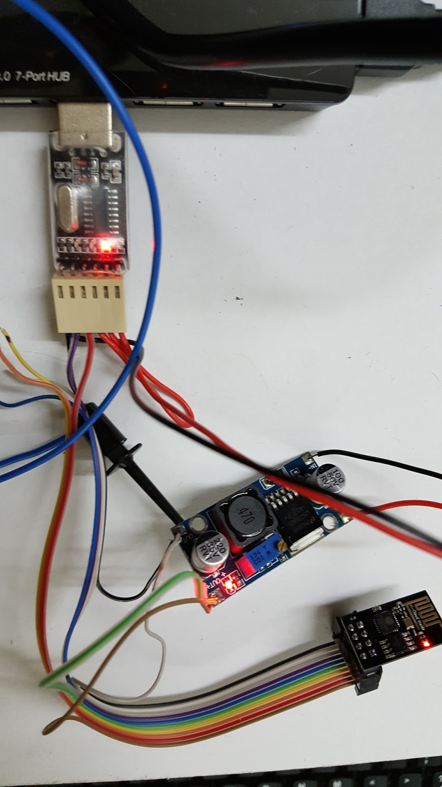
CH340 USB to serial TTL dongle, LM2596 buck converter and the ESP-01
Julian Hartline has an excellent post on this.

My ESP-01 from JFR Technologies turned out to be a rather ancient one - which probably explains the low price.

I used this CH340G serial TTL dongle, which also put out a 5V pin. This I used to power the ESP-01 via an LM2596 buck converter.

The main problem was with the 5V power into this whole assembly. The power required to program the ESP-01 is more than that of simply getting it to run. I had to plug it directly into my 3A externally powered USB 3.0 hub.  If I used a USB extension or a USB volt/current meter it would run up but fail to program.

Lastly it is worth repeating:
1. Select the 'Tools->Board->Generic ESP8266 Module' option in Arduino IDE
2. Set the upload speed to 9600 (most newer ESO-01 use 115200. My ESP-01 was 115200 during normal run but 9600 during program upload
2. Pull down GPIO0
3. Reset the ESP-01 by pulling down RST then releasing. The blue blinkenlight should flash.
4. Launch the upload 'Sketch->Upload'

Happy Trails.

Tuesday, 20 March 2018

IoT Relay/Switch using the ESP8266 NodeMCU ESP-12E Lua V3 and Arduino IDE

IoT Switch: From top: 5V relay PCB, Level Translator PCB and ESP-12E
As mentioned in an earlier post, lighting up a LED is very similar to controlling a relay. In place of the relay, we use a relay PCB with an optically-isolated input. I bought mine for RM9.99 from here.

5V opto-isolated Relay PCB
Since the ESP8266 ESP-12E is a 5V device, we need to translate its output to 5V. I am usually inclined to use a 1.8V zener diode like the TZS4678-GS08, costing some RM1.14. However an Arduino-type 4-channel  level converter is only RM1.35.

4-Channel Logic Level Converter
Unlike the resistor network or the zener diode method, this is an active circuit and uses the MOSFET BSS138:


There is a full explanation on the schematic here.

The wiring is quite straightforward:

ESP-12E    Level Converter   2-Channel Relay
3.3V           LV             HV        5V
GND          GND         GND      GND
D6              LV1           HV1      IN1
D7              LV2           HV2      IN2

Top wiring to ESP-12E, bottom wiring to 5V Relay PCB
The program, a Lua 'sketch' for the Arduino IDE, is much the same as the last post, tweaked a little to add a second channel. The only fiddle here is if we used D5, it seems to interfere with the programming of the ESP-12E via its USB serial port. If you do use D5, simply disconnect the level translator from the ESP-12E before you program it.

/*
 *  This sketch demonstrates how to set up a simple HTTP-like server.
 *  The server will set a GPIO pin depending on the request
 *    http://server_ip:8080/gpio/0 will set the GPIO2 low,
 *    http://server_ip:8080/gpio/1 will set the GPIO2 high
 *  server_ip is the IP address of the ESP8266 module, will be
 *  printed to Serial when the module is connected.

static const uint8_t D0 = 16;
static const uint8_t D1 = 5;
static const uint8_t D2 = 4;
static const uint8_t D3 = 0;
static const uint8_t D4 = 2;
static const uint8_t D5 = 14;
static const uint8_t D6 = 12;
static const uint8_t D7 = 13;
static const uint8_t D8 = 15;
static const uint8_t D9 = 3;
static const uint8_t D10 = 1;
*/


#include <ESP8266WiFi.h>

const char* ssid = "YourAcessPoint";
const char* password = "YourSecretPassword";

// Create an instance of the server
// specify the port to listen on as an argument
WiFiServer server(8080);

void setup() {
  Serial.begin(115200);
  delay(10);

  // prepare GPIO
  pinMode(D6, OUTPUT);
  pinMode(D7, OUTPUT);
  digitalWrite(D6, HIGH);
  digitalWrite(D7, HIGH);
  Serial.println("Relays off");

  // Connect to WiFi network
  Serial.println();
  Serial.print("Connecting to ");
  Serial.println(ssid);

  WiFi.mode(WIFI_STA);
  WiFi.begin(ssid, password);

  while (WiFi.status() != WL_CONNECTED) {
    delay(500);
    Serial.print(".");
  }
  Serial.println("");
  Serial.println("WiFi connected");

  // Start the server
  server.begin();
  Serial.println("Server started");

  // Print the IP address
  Serial.println(WiFi.localIP());
}

int val = 1;
int val2 = 1;

void loop() {
  // Check if a client has connected
  WiFiClient client = server.available();
  if (!client) {
    return;
  }

  // Wait until the client sends some data
  Serial.println("new client");
  while(!client.available()){
    delay(1);
  }

  // Read the first line of the request
  String req = client.readStringUntil('\r');
  Serial.println(req);
  client.flush();

  // Match the request
  String s = "";
  // Prepare the response
  Serial.print("Input string is ");
  Serial.println(req);
  if (req.indexOf("/D6/0") != -1) {
    val = 0;
    s = "HTTP/1.1 200 OK\r\nContent-Type: text/html\r\n\r\n<!DOCTYPE HTML>\r\n<html>\r\nD6 is now ";
    s += (val)?"high":"low";
    s += "</html>\n";
  }
  else if (req.indexOf("/D6/1") != -1) {
    val = 1;
    s = "HTTP/1.1 200 OK\r\nContent-Type: text/html\r\n\r\n<!DOCTYPE HTML>\r\n<html>\r\nD6 is now ";
    s += (val)?"high":"low";
    s += "</html>\n";
  }
  else if (req.indexOf("/D7/0") != -1) {
    val2 = 0;
    s = "HTTP/1.1 200 OK\r\nContent-Type: text/html\r\n\r\n<!DOCTYPE HTML>\r\n<html>\r\nD7 is now ";
    s += (val2)?"high":"low";
    s += "</html>\n";
  }
  else if (req.indexOf("/D7/1") != -1) {
    val2 = 1;
    s = "HTTP/1.1 200 OK\r\nContent-Type: text/html\r\n\r\n<!DOCTYPE HTML>\r\n<html>\r\nD7 is now ";
    s += (val2)?"high":"low";
    s += "</html>\n";
  }
  else if (req.indexOf("/index.html") != -1) {
    s = "HTTP/1.1 200 OK\r\nContent-Type: text/html\r\n\r\n<!DOCTYPE HTML>\r\n<html>\r\nHello, world.</html>\n";
  }
  else if (req.indexOf("/favicon.ico") != -1) {
    Serial.println("End of command");
    client.stop();
  }

  else {
    s = "HTTP/1.1 200 OK\r\nContent-Type: text/html\r\n\r\n<!DOCTYPE HTML>\r\n<html>\r\nInvalid request: ";
    s += req;
    s += "</html>\n";
    Serial.println("invalid request");
    Serial.println(req);
    client.print(s);
    delay(10);
    client.stop();
    return;
  }

  // Set GPIO2 according to the request
  if (val == 0)
    digitalWrite(D6, LOW);
  if (val == 1)
    digitalWrite(D6, HIGH);
  if (val2 == 0)
    digitalWrite(D7, LOW);
  if (val2 == 1)
    digitalWrite(D7, HIGH);

  client.flush();

  // Send the response to the client
  client.print(s);
  delay(1);
  Serial.println("Client disonnected");

  // The client will actually be disconnected
  // when the function returns and 'client' object is destroyed
}

As before, you turn on the first relay using:
http://yourIPaddress/D6/0

And off using:
http://yourIPaddress/D6/1

The commands for the second relay are:
http://yourIPaddress/D7/0
http://yourIPaddress/D7/1

The total cost of the parts was something like RM21.90 + RM9.99 + RM1.35 or RM33.24, not counting the 5V power supply and  the various bits of wires and connectors.

This is very similar to the Sonoff ITEAD IoT switch which sells for only RM30.84:

Sonoff ITEAD
There you have it: your DIY IoT switch actually sets you back some RM2.40. But as we shall see later, the Sonoff, among others, has some serious security problems, like the Krack exploit. Rolling our own IoT relay switch is the first step to taking control of our IoT security, rather than relying on the vendors' updates, both of the firmware and the accompanying app.

You can actually upgrade the Sonoff firmware yourself. Happy trails.  

Saturday, 10 March 2018

SPI Master & Slave Programs with the ESP8266 NodeMCU ESP-12E Lua V3 and Arduino IDE

ESP-12E as SPI Master (top) and SPI Slave (bottom)
After learning how to program the ESP8266 using the Arduino IDE, I thought it might be a good idea to interface the ESP8266 with Arduino-family devices. There are plenty of articles in the Web on interfacing the ESP8266 with Arduino CPUs like the Uno but comparatively few on interfacing to Arduino non-CPU PCBs.

PCBs like this relay boards are easy to interface to; you use the same method as the blinking LED sketch in my last post.
This 5V Arduino relay module costs as little as RM5

But other PCBs like this MAX7219 LED 7-segment Display costs a mere RM9.60 and uses the SPI or Serial Peripheral Interface:

MAX7219 LED 7-segment display module
 Quite a few PCBs use the I2C interface, including this delicious RM5.90 realtime clock:

PCF8563T Realtime Clock

SPI involves a master device and a slave device. I used an ESP-12E for both. The master code from the Arduino IDE "Examples->SPISlave->SPISlave_SafeMaster" menu works and is reproduced here as the code tends to change from version to version:

/*
    SPI Safe Master Demo Sketch
    Connect the SPI Master device to the following pins on the esp8266:

    GPIO    NodeMCU   Name  |   Uno
   ===================================
     15       D8       SS   |   D10
     13       D7      MOSI  |   D11
     12       D6      MISO  |   D12
     14       D5      SCK   |   D13

    Note: If the ESP is booting at a moment when the SPI Master has the Select line HIGH (deselected)
    the ESP8266 WILL FAIL to boot!
    This sketch tries to go around this issue by only pulsing the Slave Select line to reset the command
    and keeping the line LOW all other time.

*/
#include <SPI.h>

class ESPSafeMaster
{
private:
    uint8_t _ss_pin;
    void _pulseSS()
    {
        digitalWrite(_ss_pin, HIGH);
        delayMicroseconds(5);
        digitalWrite(_ss_pin, LOW);
    }
public:
    ESPSafeMaster(uint8_t pin):_ss_pin(pin) {}
    void begin()
    {
        pinMode(_ss_pin, OUTPUT);
        _pulseSS();
    }

    uint32_t readStatus()
    {
        _pulseSS();
        SPI.transfer(0x04);
        uint32_t status = (SPI.transfer(0) | ((uint32_t)(SPI.transfer(0)) << 8) | ((uint32_t)(SPI.transfer(0)) << 16) | ((uint32_t)(SPI.transfer(0)) << 24));
        _pulseSS();
        return status;
    }

    void writeStatus(uint32_t status)
    {
        _pulseSS();
        SPI.transfer(0x01);
        SPI.transfer(status & 0xFF);
        SPI.transfer((status >> 8) & 0xFF);
        SPI.transfer((status >> 16) & 0xFF);
        SPI.transfer((status >> 24) & 0xFF);
        _pulseSS();
    }

    void readData(uint8_t * data)
    {
        _pulseSS();
        SPI.transfer(0x03);
        SPI.transfer(0x00);
        for(uint8_t i=0; i<32; i++) {
            data[i] = SPI.transfer(0);
        }
        _pulseSS();
    }

    void writeData(uint8_t * data, size_t len)
    {
        uint8_t i=0;
        _pulseSS();
        SPI.transfer(0x02);
        SPI.transfer(0x00);
        while(len-- && i < 32) {
            SPI.transfer(data[i++]);
        }
        while(i++ < 32) {
            SPI.transfer(0);
        }
        _pulseSS();
    }

    String readData()
    {
        char data[33];
        data[32] = 0;
        readData((uint8_t *)data);
        return String(data);
    }

    void writeData(const char * data)
    {
        writeData((uint8_t *)data, strlen(data));
    }
};

ESPSafeMaster esp(SS);

void send(const char * message)
{
    Serial.print("Master: ");
    Serial.println(message);
    esp.writeData(message);
    delay(10);
    Serial.print("Slave: ");
    Serial.println(esp.readData());
    Serial.println();
}

void setup()
{
    Serial.begin(115200);
    SPI.begin();
    esp.begin();
    delay(1000);
    send("Hello Slave!");
}

void loop()
{
    delay(1000);
    send("Are you alive?");
}

Unfortunately the "Examples->SPISlave->SPISlave_Test" did not work for me. The Slave could read the master but its reply seems corrupted. Luckily I found a working version in the ESP8266 Community Forum:

/*
    SPI Slave Demo Sketch
    Connect the SPI Master device to the following pins on the esp8266:

    GPIO    NodeMCU   Name  |   Uno
  ===================================
     15       D8       SS   |   D10
     13       D7      MOSI  |   D11
     12       D6      MISO  |   D12
     14       D5      SCK   |   D13

    Note: If the ESP is booting at a moment when the SPI Master has the Select li
ne HIGH (deselected)
    the ESP8266 WILL FAIL to boot!
    See SPISlave_SafeMaster example for possible workaround

*/

#include "SPISlave.h"

void setup()
{
    Serial.begin(115200);
    Serial.setDebugOutput(true);
    Serial.println();

    // data has been received from the master. Beware that len is always 32
    // and the buffer is autofilled with zeroes if data is less than 32 bytes long
    // It's up to the user to implement protocol for handling data length
    SPISlave.onData([](uint8_t * data, size_t len) {
        String message = String((char *)data);
        char answer[33];
        if(message.equals("Hello Slave!")) {
            strcpy(answer, "Hello Master!");
        } else if(message.equals("Are you alive?")) {
            sprintf(answer, "Alive for %u seconds!", millis() / 1000);
        } else {
            strcpy(answer, "Say what?");
        }
        SPISlave.setData(answer);
        Serial.printf("Question: %s\Answer: %s\n", (char *)data, answer);
    });

    // The master has read out outgoing data buffer
    // that buffer can be set with SPISlave.setData
    SPISlave.onDataSent([]() {
        Serial.println("Answer Sent");
    });

    // status has been received from the master.
    // The status register is a special register that bot the slave and the master can write to and read from.
    // Can be used to exchange small data or status information
    SPISlave.onStatus([](uint32_t data) {
        Serial.printf("Status: %u\n", data);
        SPISlave.setStatus(millis()); //set next status
    });

    // The master has read the status register
    SPISlave.onStatusSent([]() {
        Serial.println("Status Sent");
    });

    // Setup SPI Slave registers and pins
    SPISlave.begin();

    // Additional setting to have MISO change on falling edge
    SPI1C2 |= 1 << SPIC2MISODM_S;

    // Set the status register (if the master reads it, it will read this value)
    SPISlave.setStatus(millis());

    // Sets the data registers. Limited to 32 bytes at a time.
    // SPISlave.setData(uint8_t * data, size_t len); is also available with the same limitation
    SPISlave.setData("Ask me a question!");
}

void loop() {}

The two ESP-12E, master and slave are wired thus:

As per the comments in the two sketches, the ESP-12E pin assignments are:

                  Master               Slave
              D8       SS      -   SS          D8
              D7      MOSI  -   MOSI    D7
              D6      MISO  -   MISO    D6
              D5      SCK    -   SCK      D5

I plugged both into the same laptop, and the slave came up as /dev/ttyUSB0 and the master /dev/ttyUSB1. By clicking on "Tools->Port" I could switch between the two serial ports and program the master and slave in turn.

When working correctly you should get the following output from the Master's Serial Monitor:

Master: Are you alive?
Slave: Alive for 44 seconds!

Master: Are you alive?
Slave: Alive for 45 seconds!

Master: Are you alive?
Slave: Alive for 46 seconds!

Master: Are you alive?
Slave: Alive for 47 seconds!

Master: Are you alive?
Slave: Alive for 48 seconds!

Now if you flipped over to /dev/ttyUSB0 and relaunched the Serial Monitor, you should get:

Question: Are you alive?Answer: Alive for 44 seconds!
Answer Sent
Question: Are you alive?Answer: Alive for 45 seconds!
Answer Sent
Question: Are you alive?Answer: Alive for 46 seconds!
Answer Sent
Question: Are you alive?Answer: Alive for 47 seconds!
Answer Sent

There you have it, SPI communication using the ESP8266 and Arduino IDE. 

Happy Trails.